¶ Creality K1 SE - KCM Set Upgrade Guide
| Image | Information |
|---|---|
 |
Welcome to the installation page for Creality K1 SE KCMSet. This guide will help you update your printer's firmware to ensure compatibility with KCMSet, download and print the required .STL files for mechanical assembly, complete the mechanical setup, and configure the Klipper settings. By following these steps, you will successfully complete the installation process. |
¶ Downloadable parts required for the installation
Before starting the installation, please download all the printable .stl files below and complete their printing.
¶ Klipper Config Files for Creality K1 SE - KCM Set
- Creality K1 SE Config Files | Download
¶ Mechanical Setup
¶ Remove the Stock Toolhead
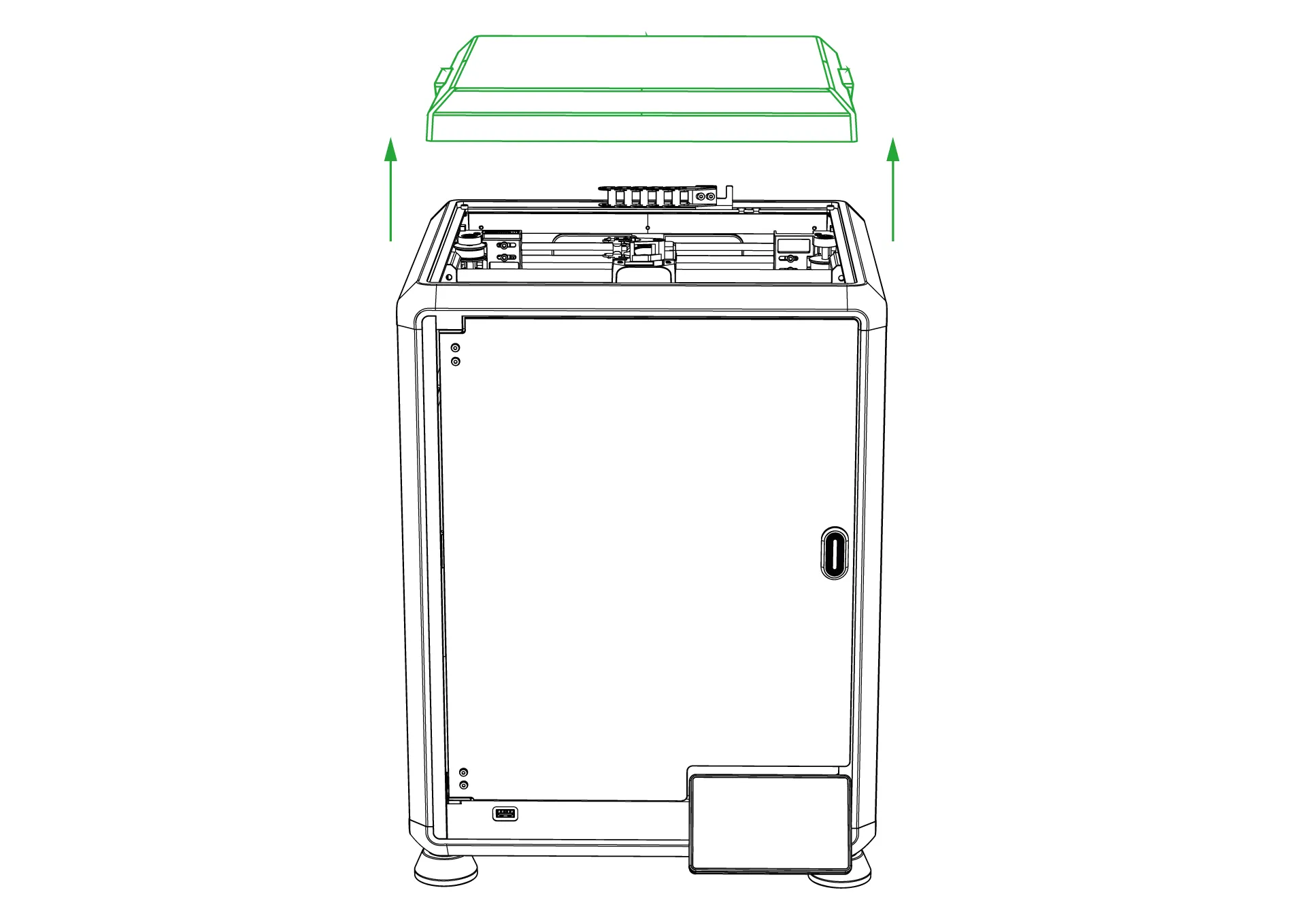
¶ 1-Remove the top cover
Remove the top cover of the K1 printer to access the stock print head.
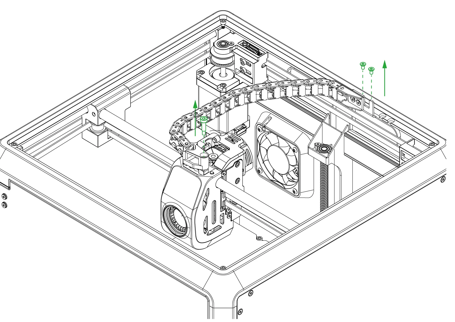
¶ 2-Remove the screws of the cable holder
Remove the two screws at the back of the cable path and the one screw on the print head.
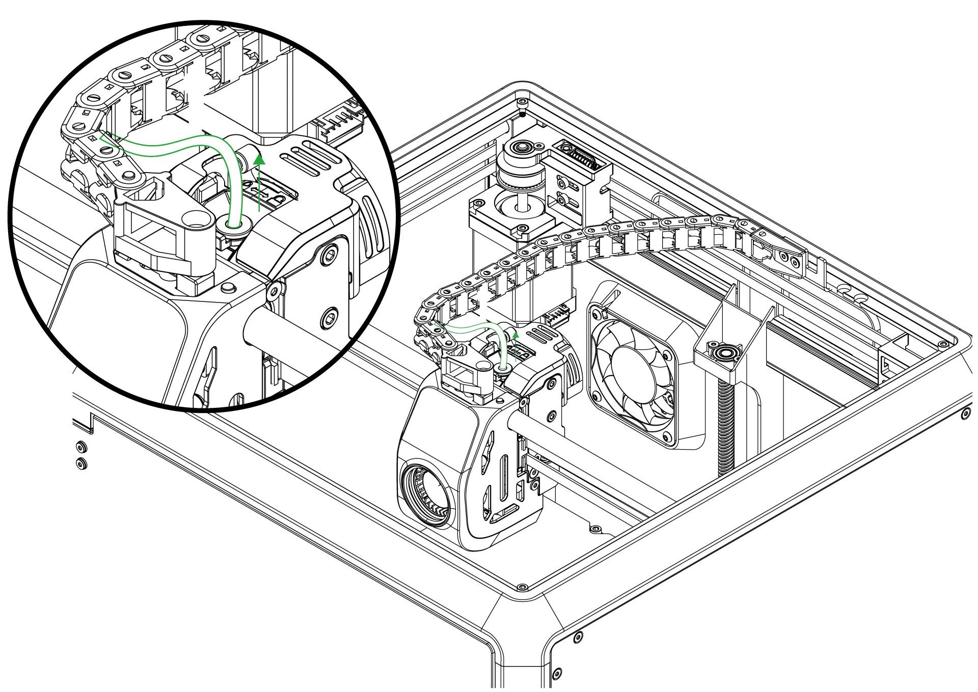
¶ 3-Remove the PTFE tube from the print head
Press the PTFE tube against the PTFE holder and pull it upwards to remove it from the print head. Make sure there is no filament inside the print head while doing this. If there is filament, the PTFE tube will not come off.
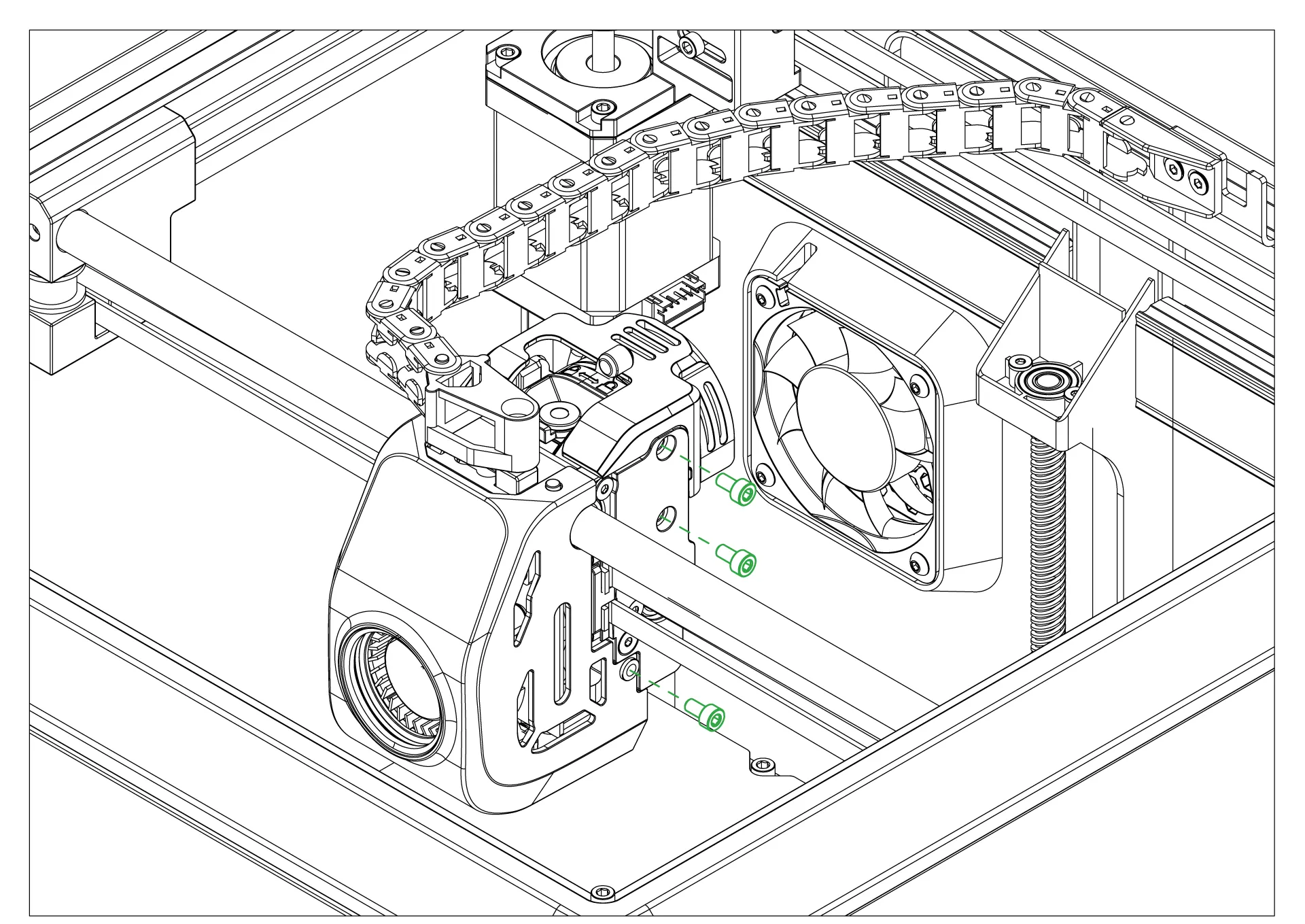
¶ 4-Remove the screws of the stock print head
Remove the 3 mounting screws on the right side of the print head and take it out.
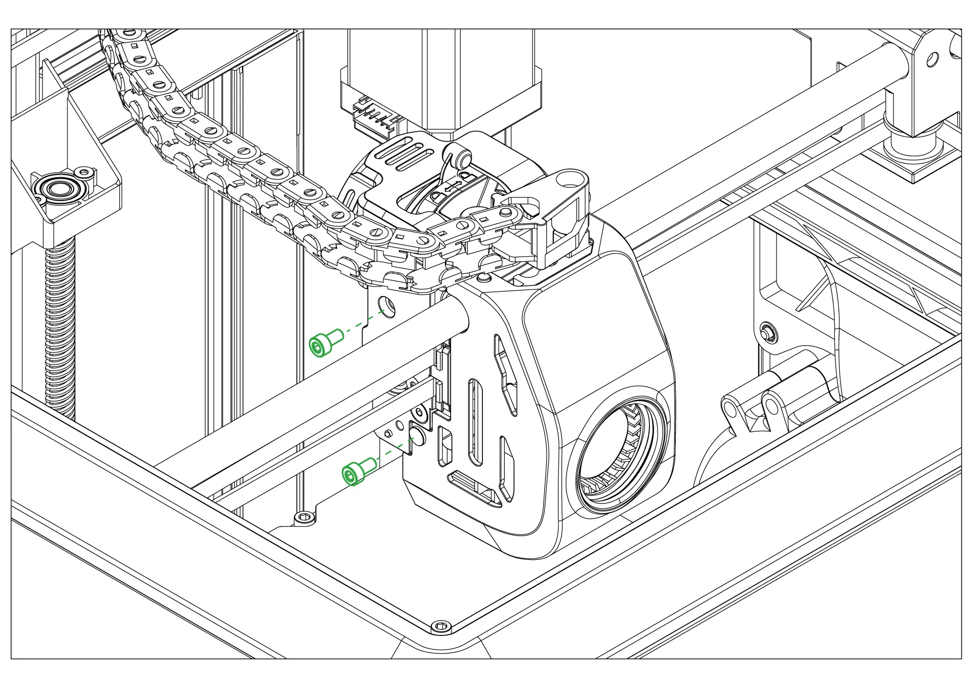
¶ 5-Remove the screws of the stock print head
Use an Allen wrench to remove the two mounting screws on the right side of the print head.
¶ 6-Remove the front cover
Pull the front cover forward to remove it, and disconnect the fan cable on the cover.
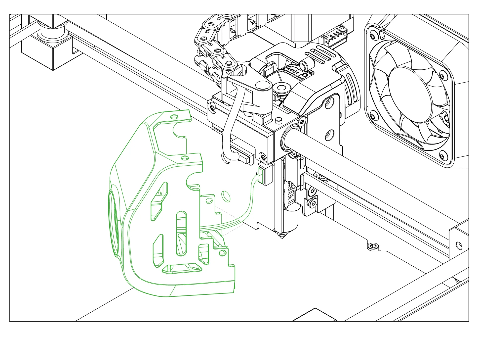
¶ 7-Disconnect the stock toolhead cable from its socket
Disconnect the stock head cable from the socket on the head control socket.
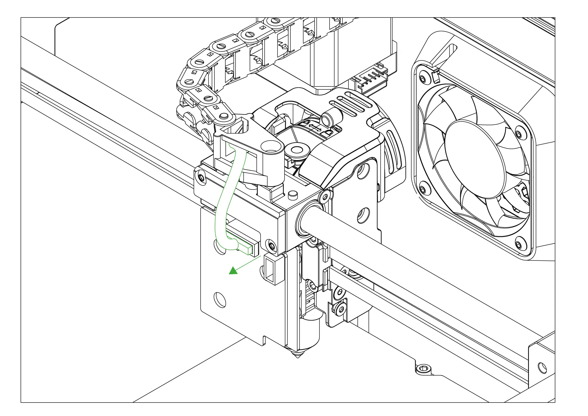
¶ 8-Remove the cable path
After disconnecting the head cable, pull the cable path upwards to remove it.

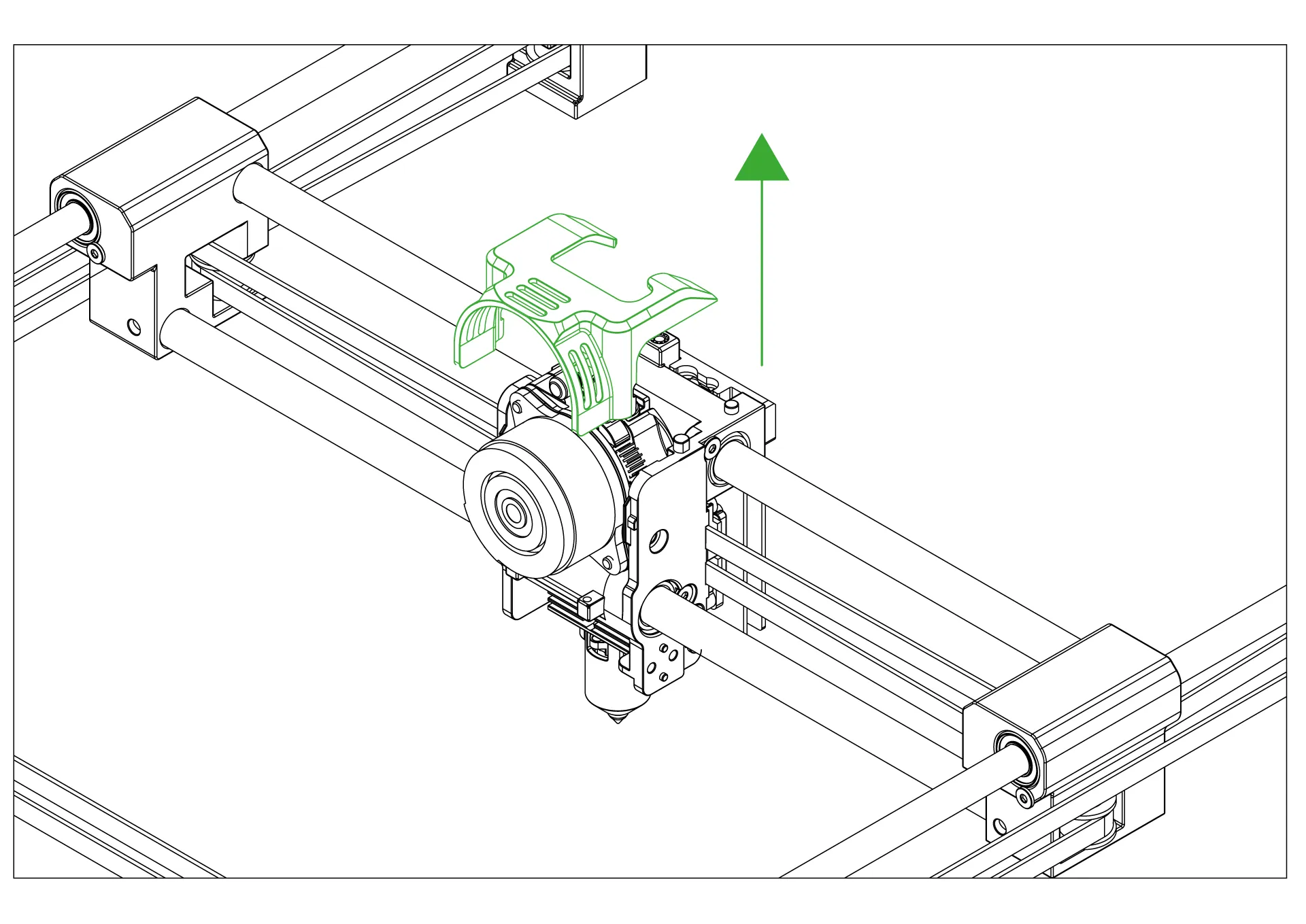
¶ 9-Remove the motor holder plastic part
Pull the plastic part that holds the motor upwards to remove it from its place.
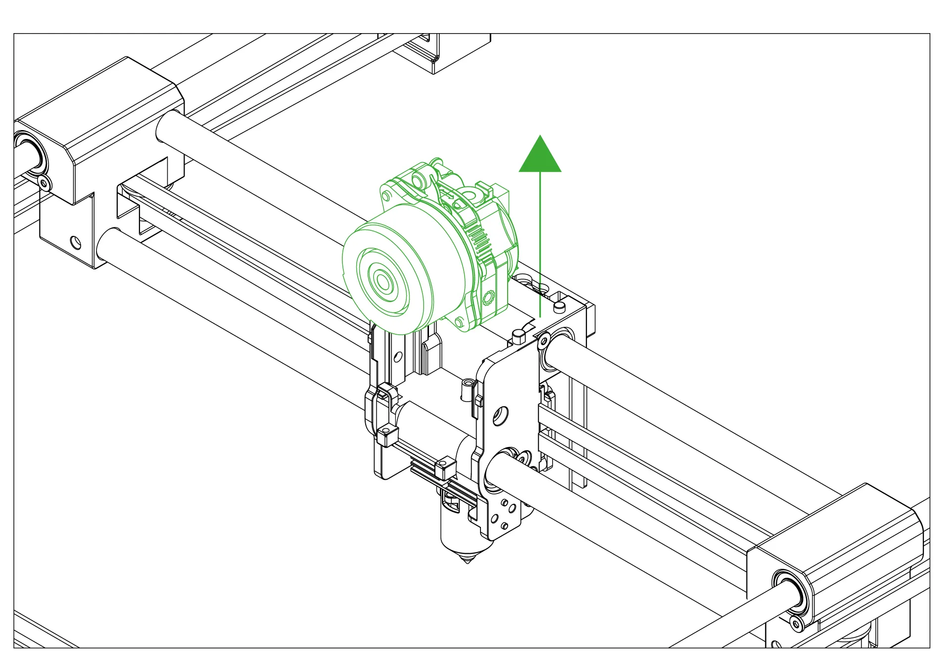
¶ 10-Remove the pancake motor
Pull the pancake motor upwards to remove it from its slot.
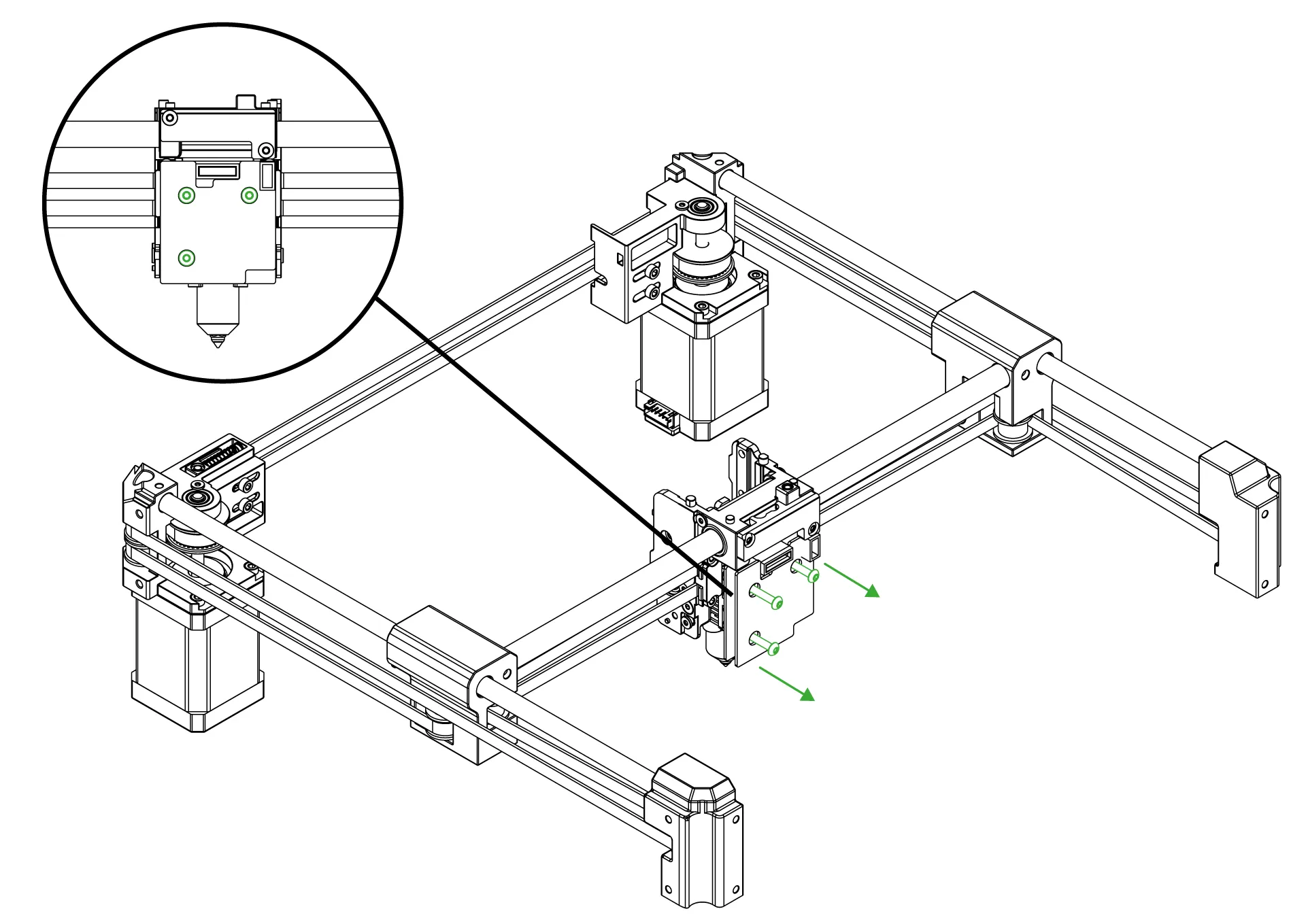
¶ 11-Remove the screws on the head control board
Use an Allen wrench to remove the three screws on the stock head control board.
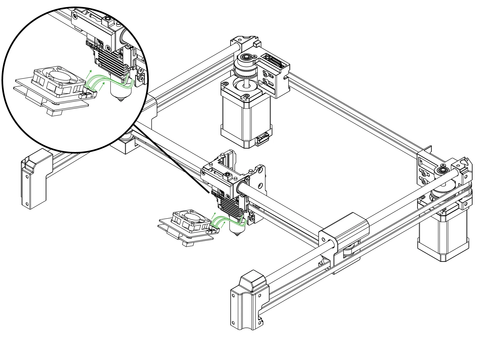
¶ 12-Disconnect the sockets on the board
Disconnect the thermistor and heater cartridge wires from their slots on the head control board.
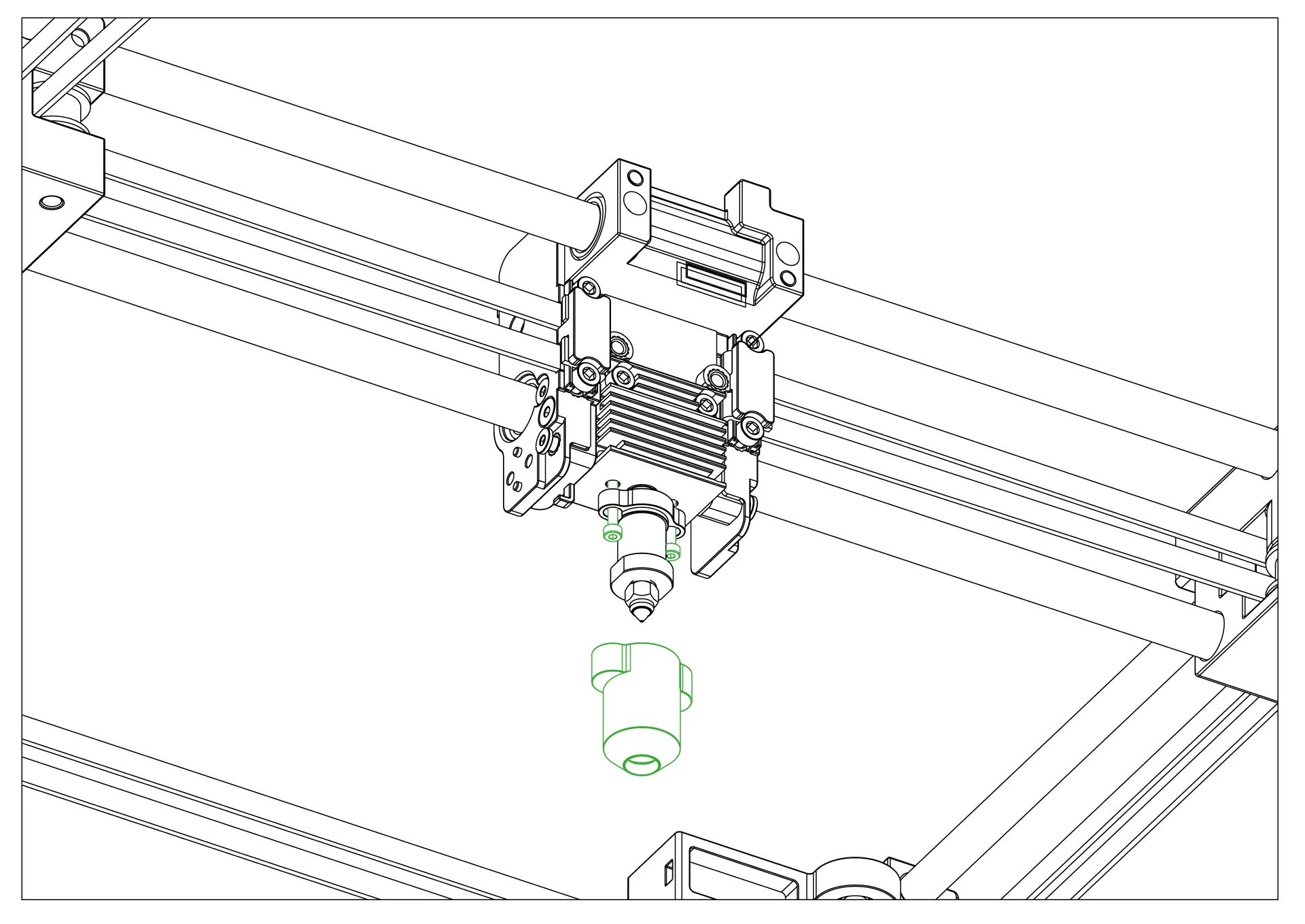
¶ 13-Remove the hotend silicone and screws
To remove the hotend, first pull the heat silicone downward to detach it. Then, remove the two screws underneath.
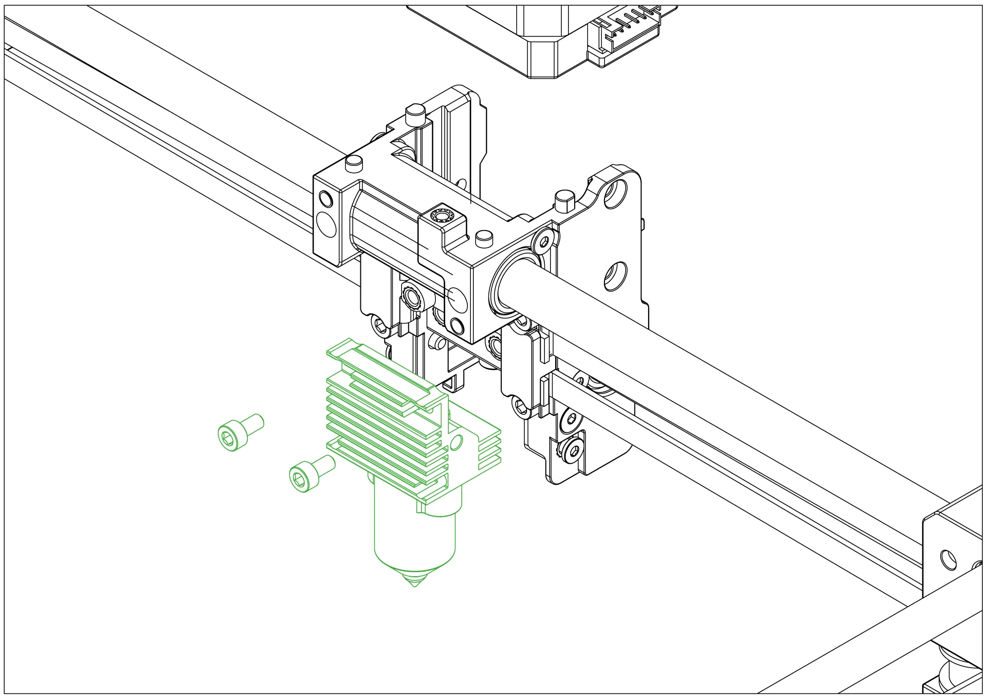
¶ 14-Remove the hotend from its place
Remove the two screws on the heatsink that secure the hotend, and then detach the hotend.
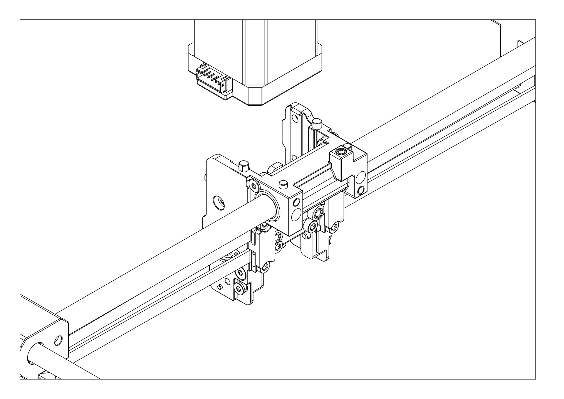
¶ 15-The stock print head disassembly is complete
You have successfully completed the disassembly until the part shown in the image. Do not remove this part. The ChromaHead will be mounted on this part.
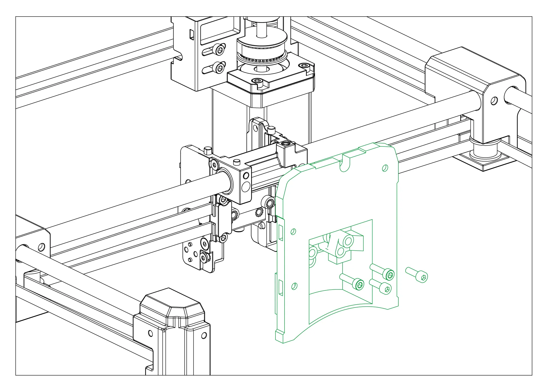
¶ 16-ChromaHead Adapter Part Mounting
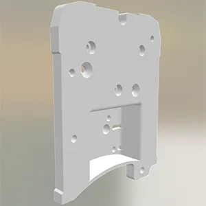
Secure the adapter part required to connect the ChromaHead to the stock carriage using 4 screws in the designated holes.
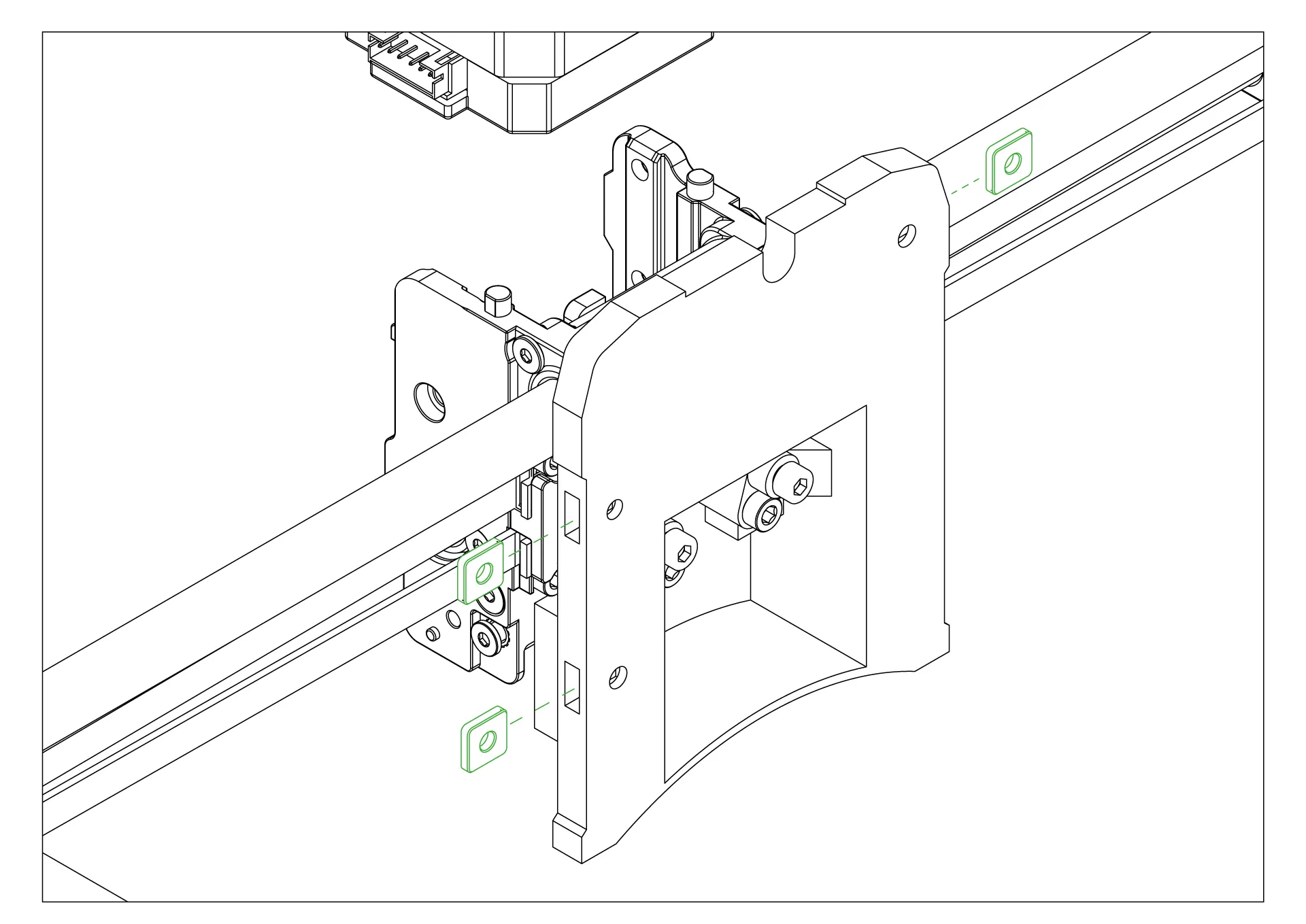
¶ 17-Adapter Part Square Nut Mounting
Place the 3 square nuts into the holes on the edges to secure the ChromaHead to the adapter part.
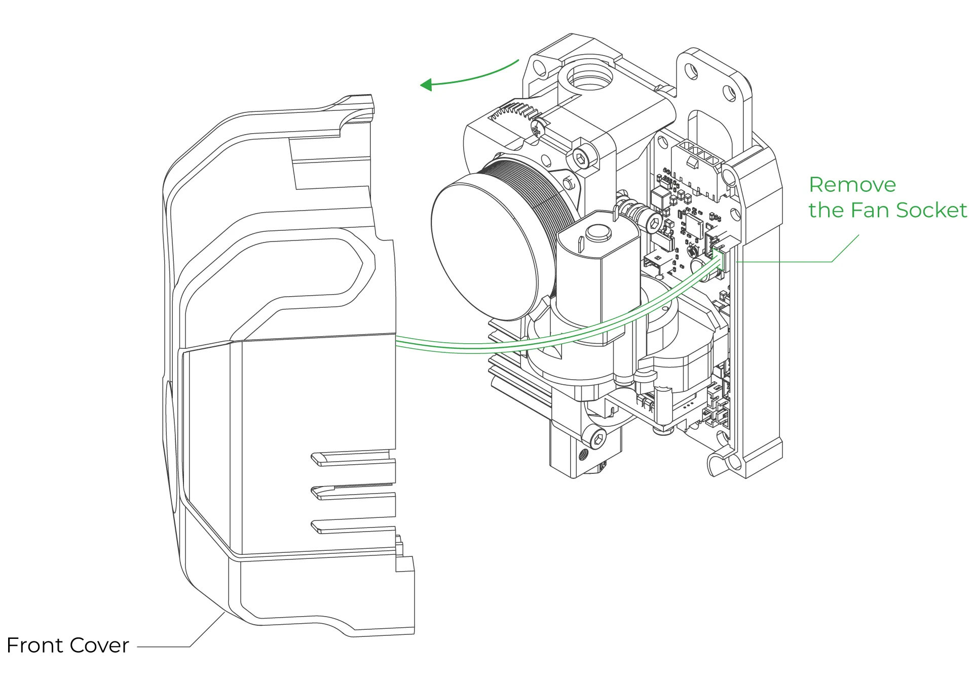
¶ 18-Remove the front cover of the ChromaHead
The connection screws for the ChromaHead's adapter part are located inside the front cover. Therefore, the front cover needs to be removed for installation.
¶ 19-Secure the ChromaHead
Secure the ChromaHead to the adapter part using 2 screws on the left side and 1 screw on the top right, as shown in the image.

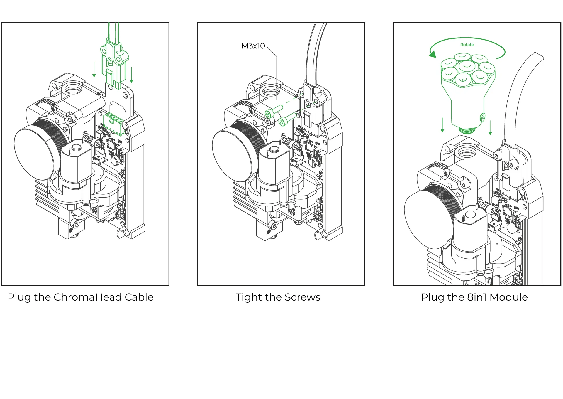
¶ 20-Head connection cable and the 8-in-1 kit mounting
Connect the head connection cable as shown in the image and make sure it is secured in place using the fastening screws. Then, rotate the 8-in-1 module and install it as shown in the image. Ensure it is tightly secured and doesn't move.
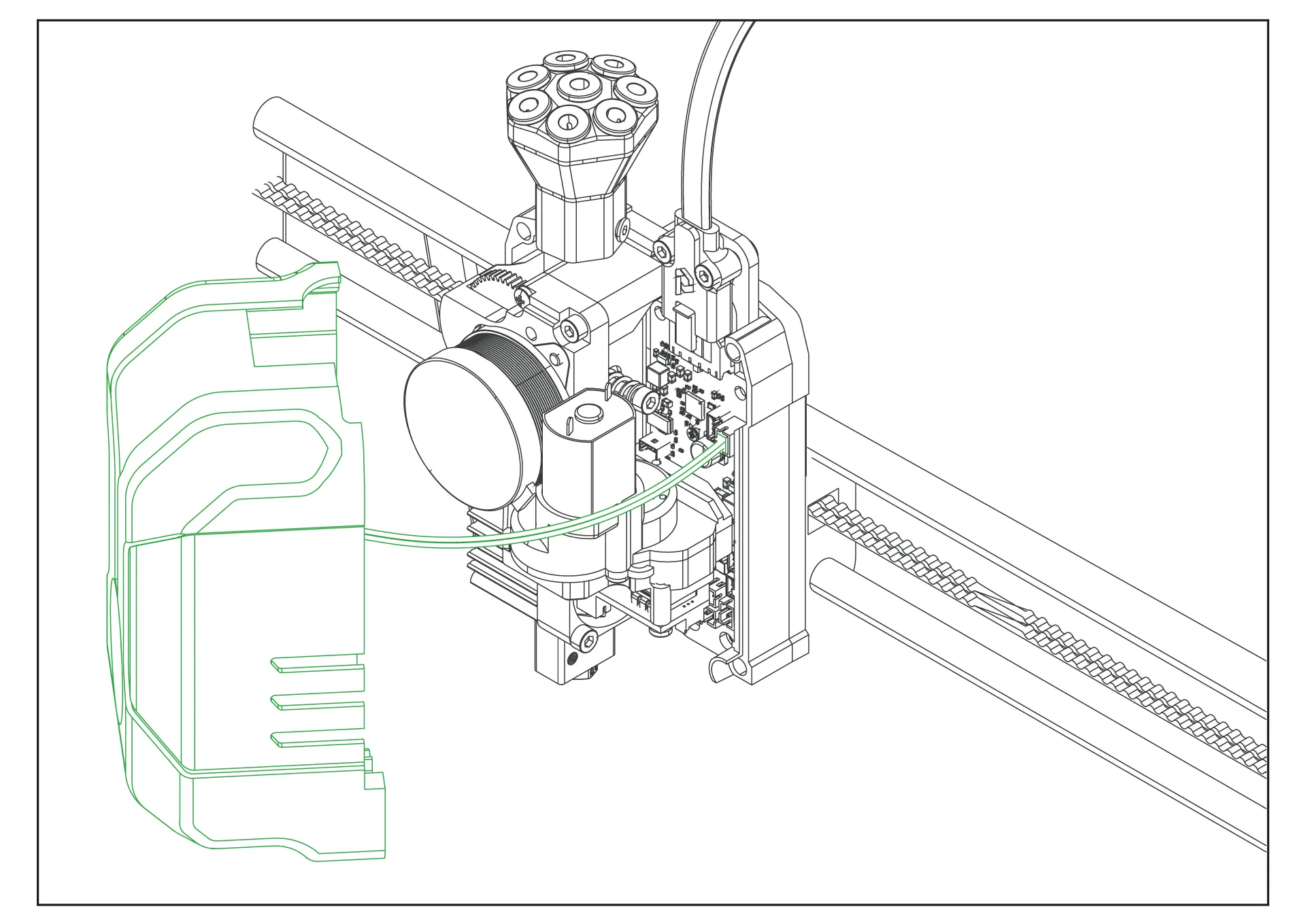
¶ 21-Close the front cover of the ChromaHead
The ChromaHead installation is complete. Reconnect the cooling fan cable from the front cover to the designated spot on the control board, and then close the cover.
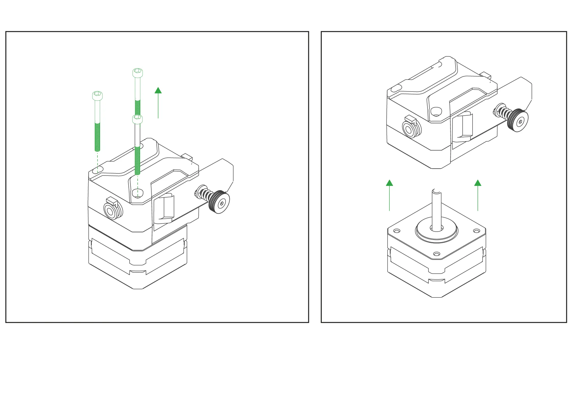
¶ 22-CX-I Extruders Installation
The CX-I Extruders come pre-assembled with the motor and plastic components inside the box. However, in order to mount them onto the 4-in-1 extruder holder, the motor and extruder sections need to be separated. To do this, remove the 3 screws on the top of the extruder and separate the motor from the extruder section.
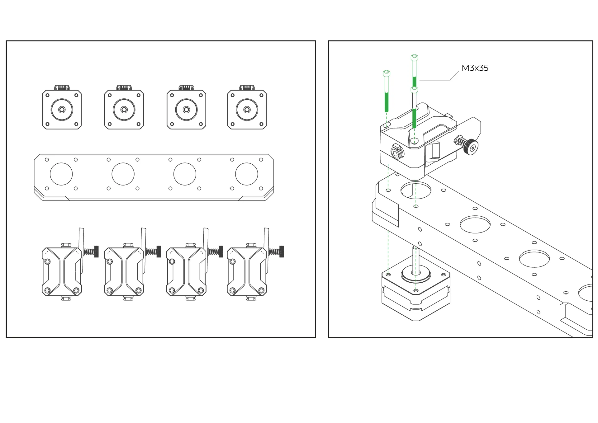
¶ 23- Place the extruders onto the 4-extruder holder.
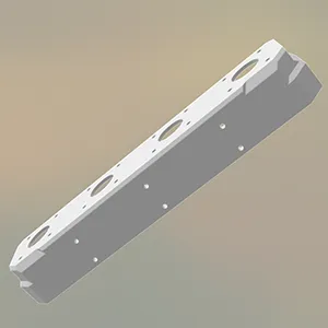
Place the extruder on the top side of the printable 4-extruder holder you downloaded. Position the stepper motor on the bottom side, and then securely fasten the extruder using the three screws on it to complete the assembly.
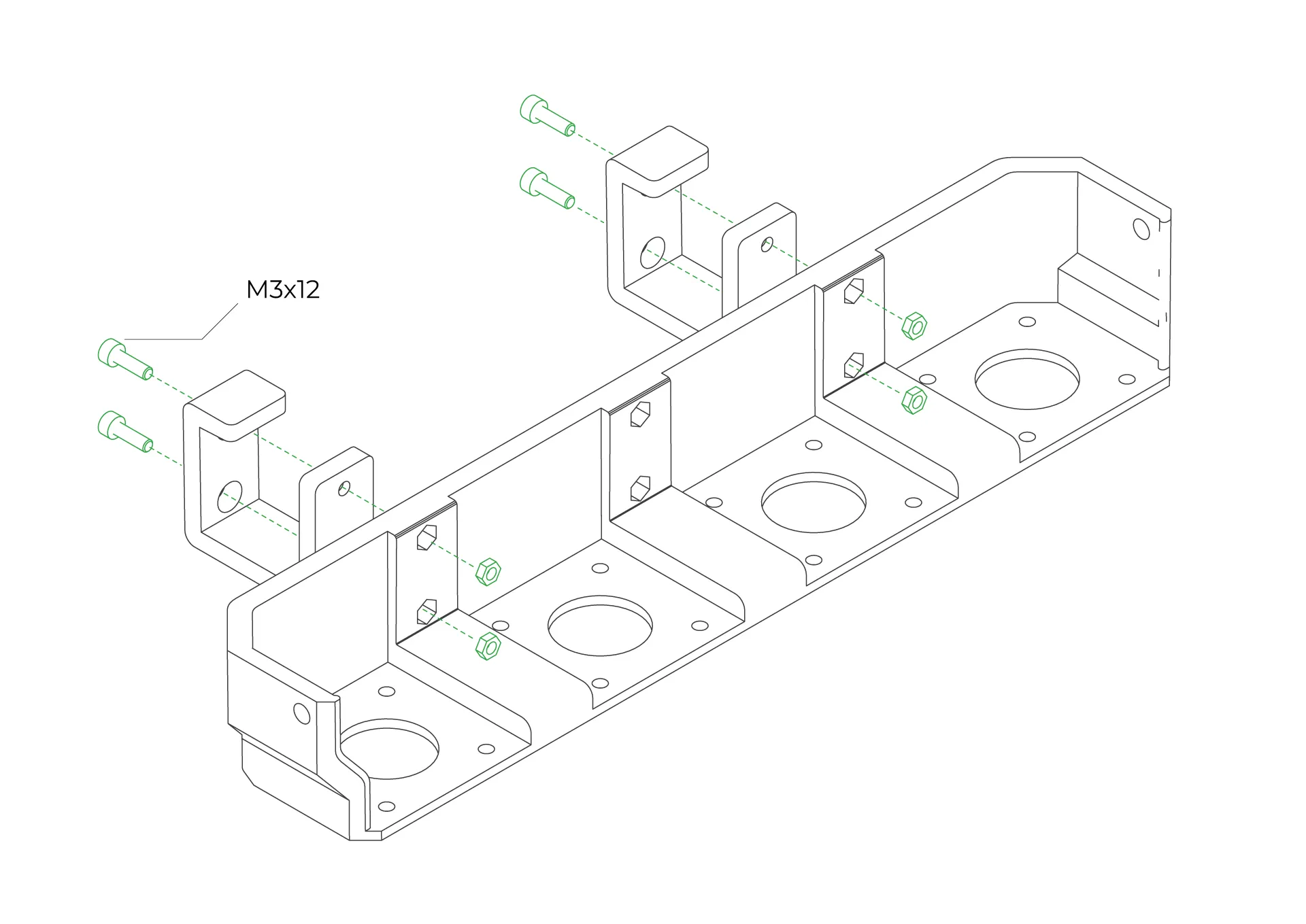
¶ 24-Attach the Mounting Feet to the 4-Extruder Holder
Secure the feet to the 4-extruder holder using M3-12mm screws and nuts.
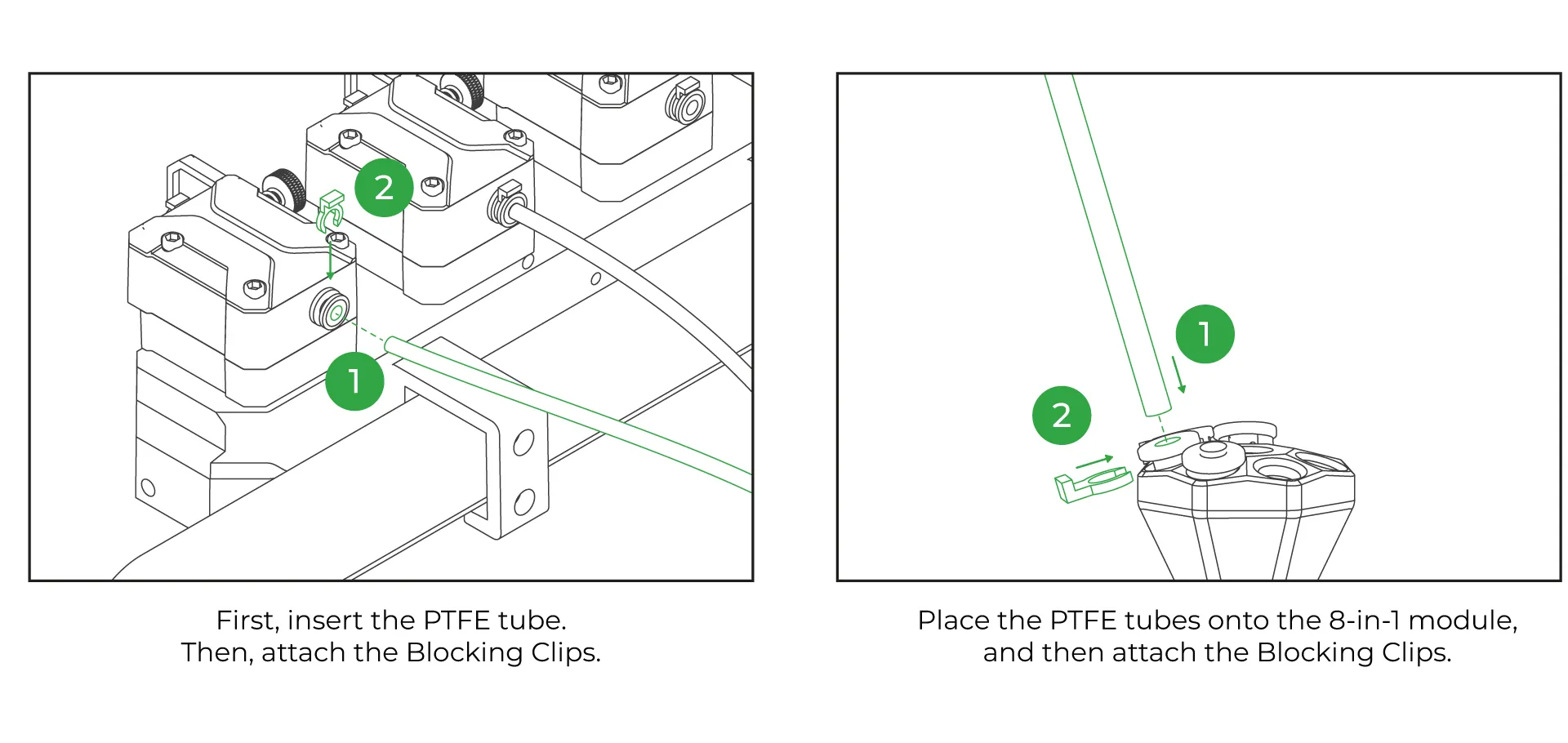
¶ 25-Install the PTFE Tubes
First, insert the PTFE tube into the CX-I extruder and secure it tightly using the blue retainers. Then, choose a nearby hole on the 8in1 and connect the other end of the PTFE tube to it, securing it firmly.
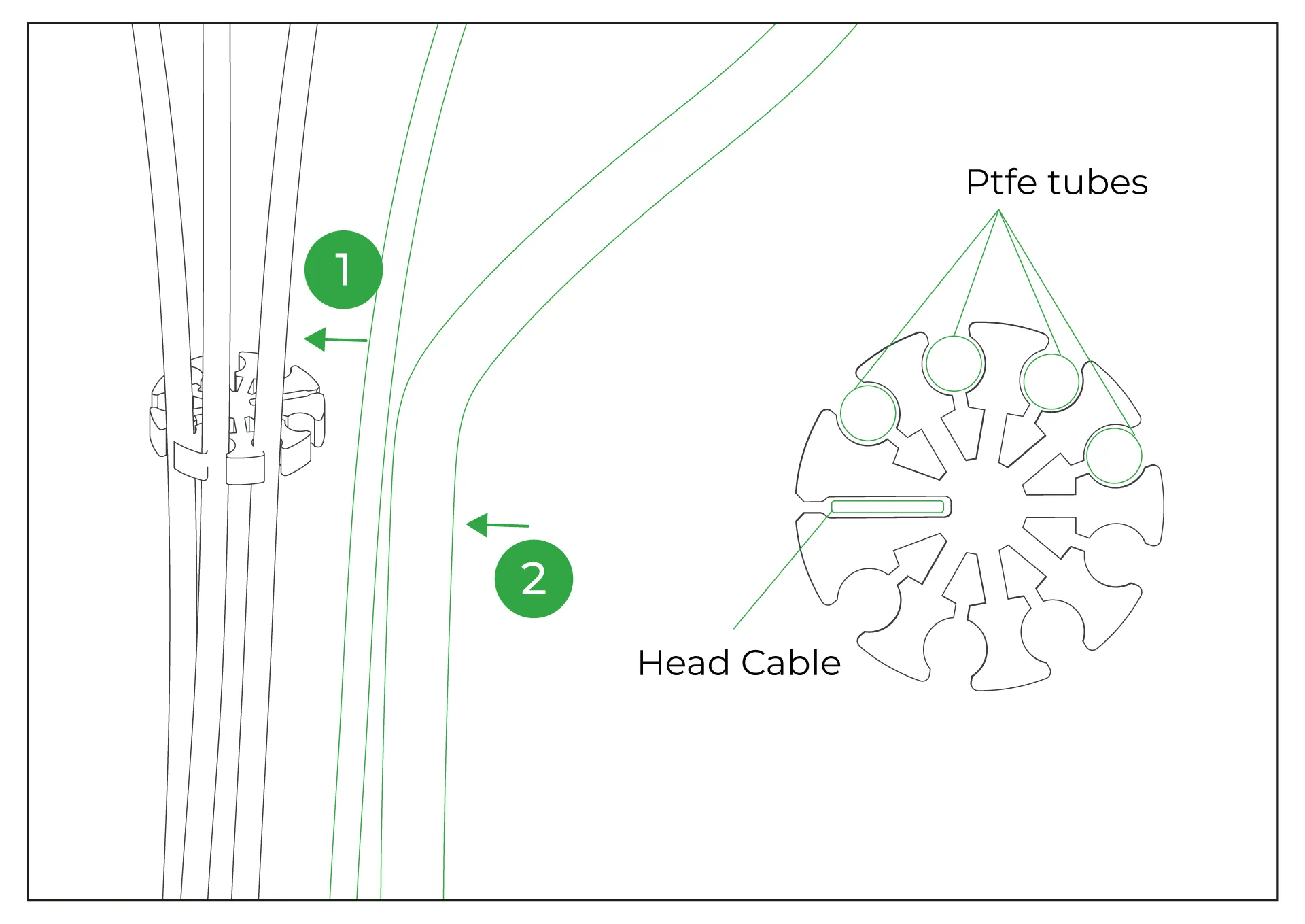
¶ 26-Place the PTFE Organizer
The PTFE organizer, provided as a printable 3D part, is designed to hold PTFE tubes together. You can secure the PTFE tubes by passing them through the slots on the organizer.
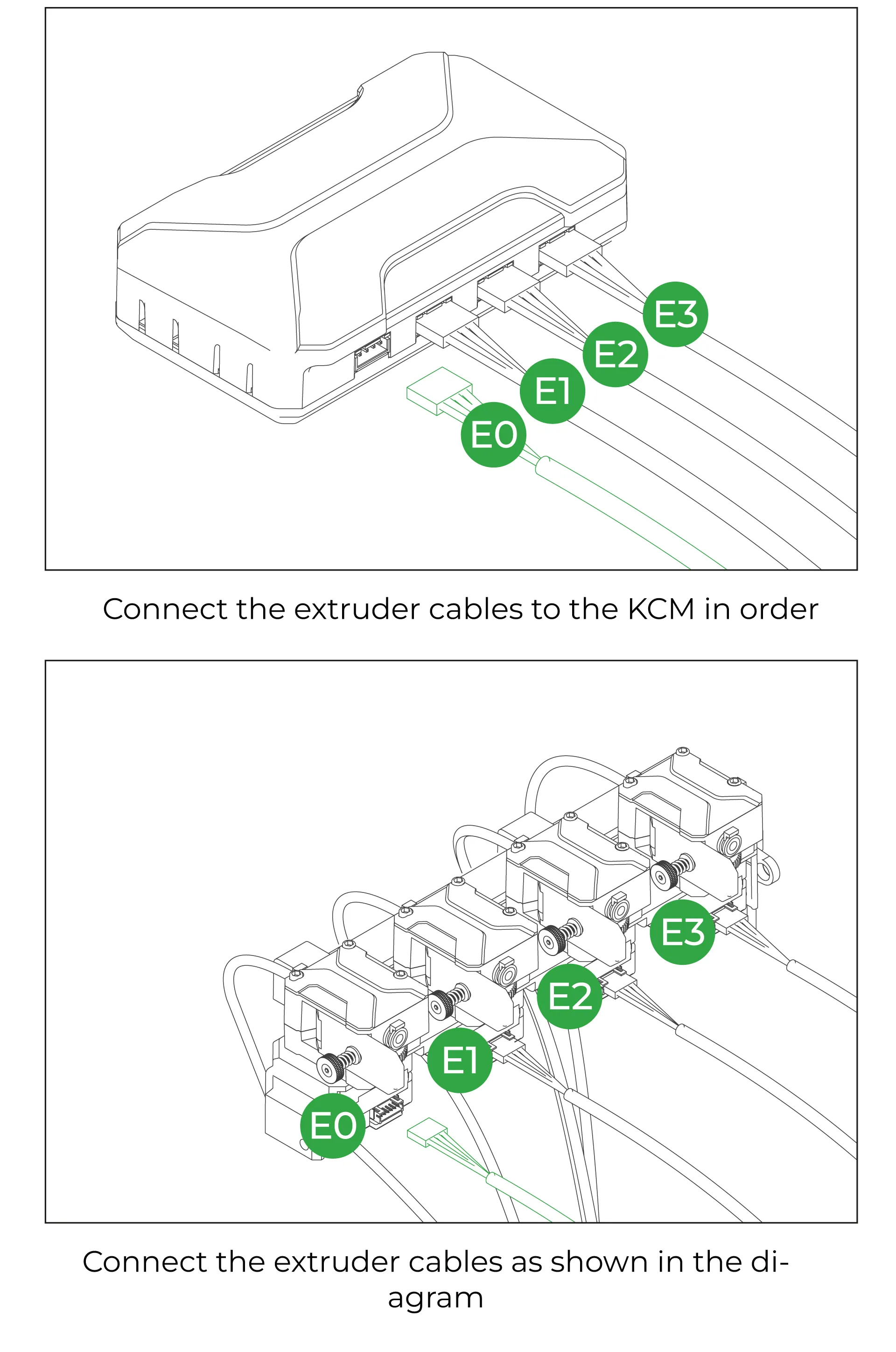
¶ 27-Plug the Extruder Motor Cables
The order of the extruder motor cables is crucial. Position the KCM with the extruder slots on the right-hand side. In this orientation, connect the first cable to the bottom-most socket. Then, proceed to connect the remaining cables in order, ensuring they are not mixed up. Connect the other ends of the cables to the extruders, starting from the left when viewed from the back of the extruders. Ensure the cables are connected in the correct order.
¶ 28-Plug the KCM to 3D Printer
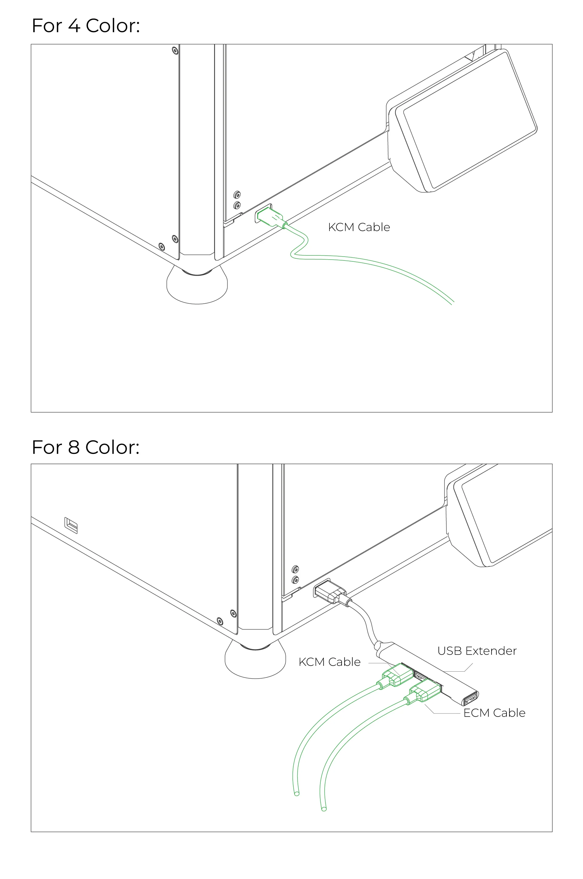
Use the USB to Type-C cable included in the box to connect the KCM to the 3D printer. If you plan to use an ECM or multiple accessories, you can use a USB hub. However, if you use a USB hub, remember that you will need to reconfigure the USB paths in the Config file.
¶ Gain Root Access
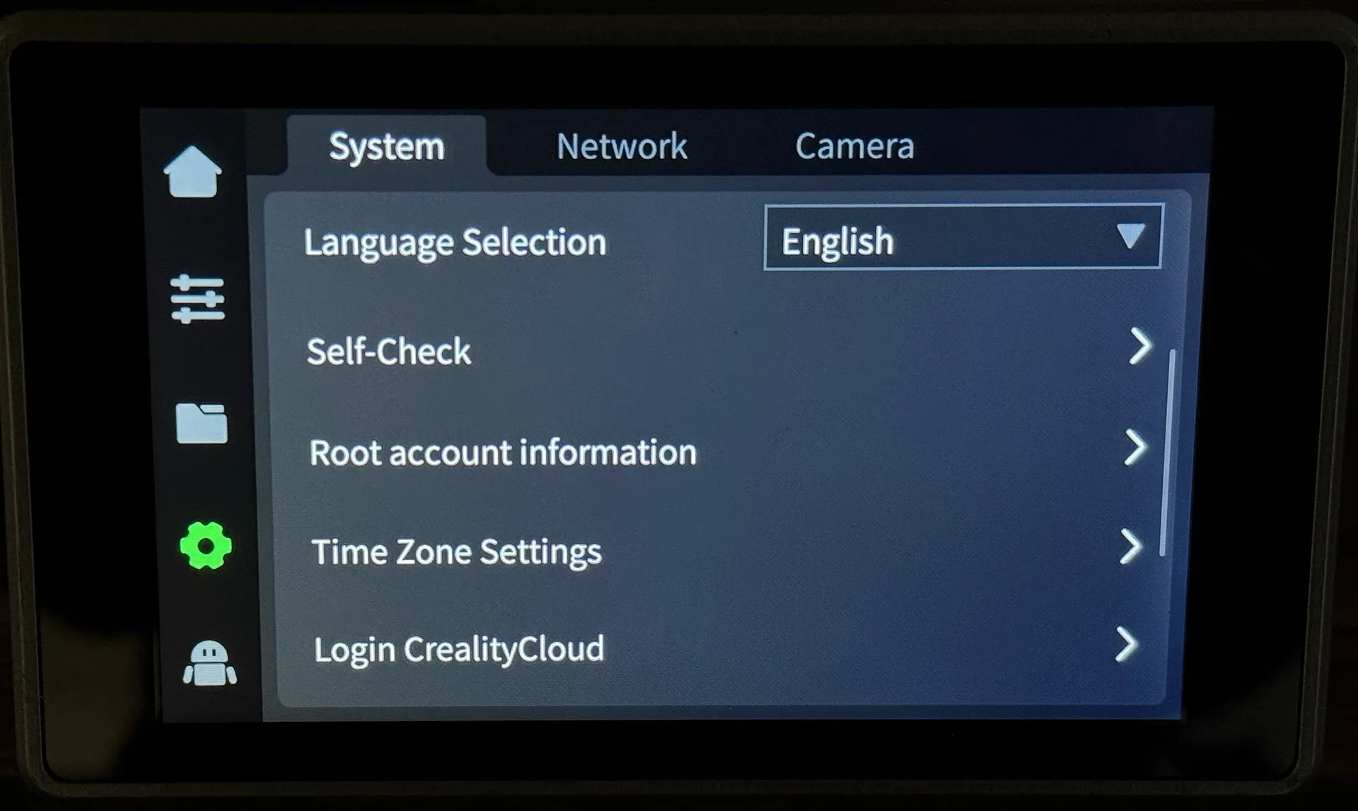
We will connect to the K1 series printer via its IP address and SSH root credentials to perform the necessary Klipper updates and configurations from the computer.
¶ Read and Acknowledge the Warning
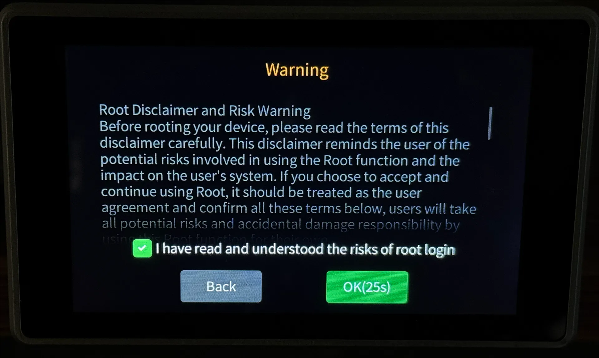
Review the potential issues that root access may cause, and acknowledge that any risks or problems arising from its use will be your responsibility.
¶ Copy the Password
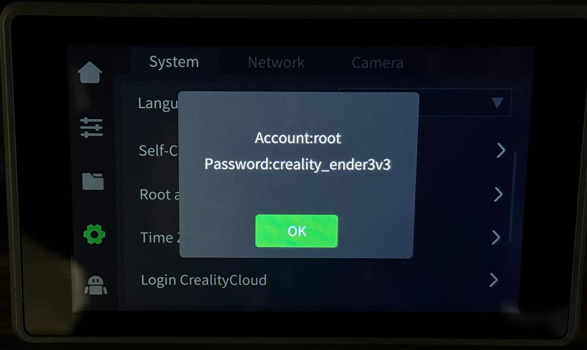
The password required for the SSH connection will be displayed on the screen. Make sure to copy and save it securely.
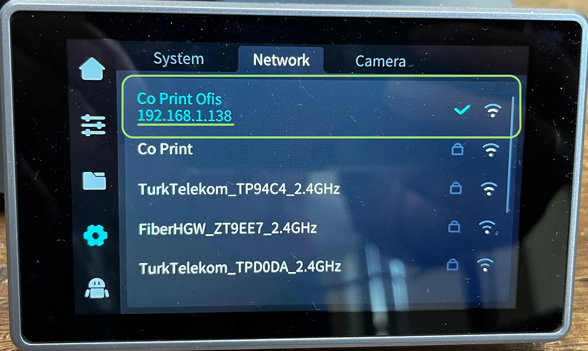
¶ Obtain the IP Address for SSH Connection
To establish an SSH connection, retrieve the printer's IP address and proceed to your computer.
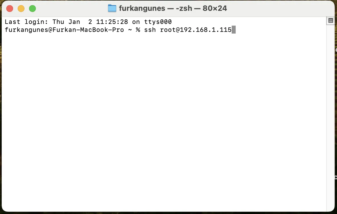
¶ Open the terminal and establish an SSH connection
Open the terminal on your computer. Then, to establish an SSH connection, type the following command:
ssh root@192.168.1.115 Here, the IP address after the @ symbol should be the one you read from your printer's screen.
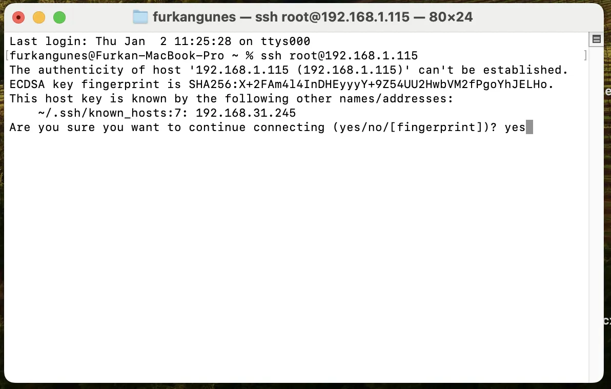
¶ Answer the security question
In the macOS operating system we are using, a secure connection warning asks whether we want to proceed with the connection. In this case, type yes to initiate the connection. This question may not appear on Windows systems.
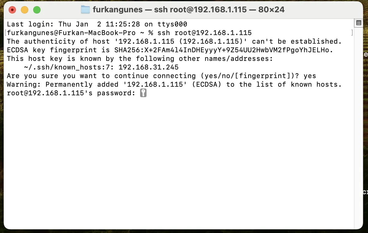
¶ Enter the root password you obtained from the printer's screen.
Please type the root access password you obtained from your printer's screen into the terminal. For security reasons, the password you type will not be displayed on the screen. Once you are sure you have entered it correctly, press the Enter key to log in.
¶ Complete the SSH connection
If you successfully log in, you will see a command prompt like this. Paste the commands here in the given order.
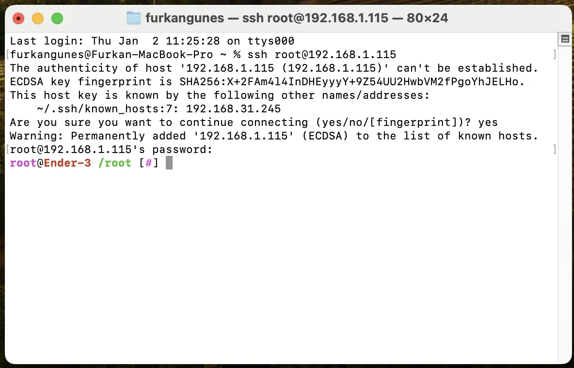
¶ Access the file location
Access the file location by typing cd /usr/data into the terminal.
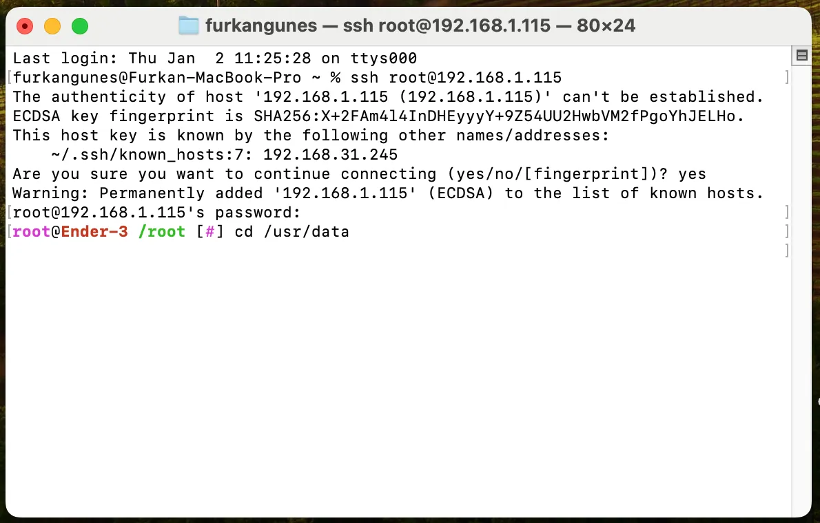
¶ Run the helper software
Run the helper program using the command:
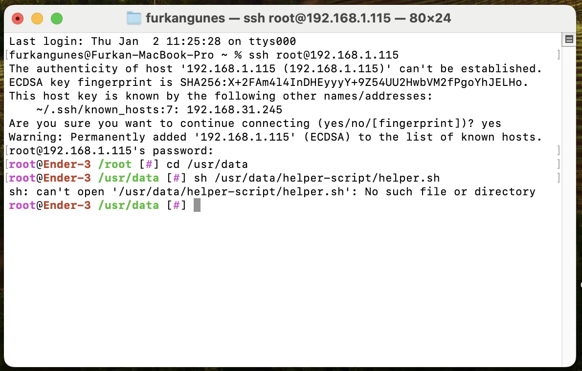
sh /usr/data/helper-script/helper.sh.
If the program is not installed, you will encounter the error:
ssh: can't open '/usr/data/helper-script/helper.sh No such file or directory'.
If you do not encounter this error, proceed directly to the next step.
For those who encounter this error, follow the instructions below:
To install the program on the system, run the following command directly from your current directory in the terminal:
git clone https://github.com/Guilouz/Creality-Helper-Script.git /usr/data/helper-script
If this command does not work, visit the Helper's official wiki page for more detailed information.
Install Helper Wiki Page.
Once the installation is complete, run the command
sh /usr/data/helper-script/helper.sh again.
This time, if the installation was successful, the following screen will appear.
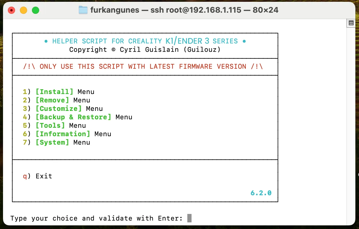
¶ Enter the Install section
Type 1 into the terminal and press the Enter key to access the install menu.
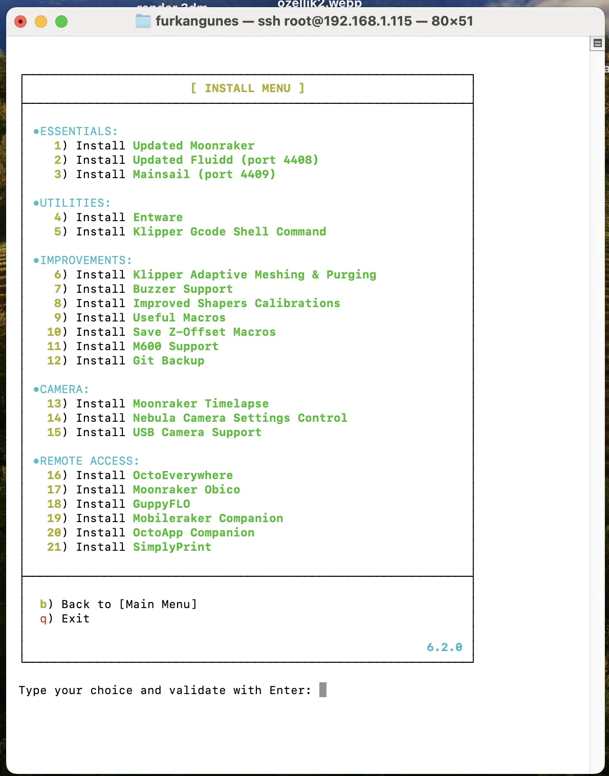
Through this menu, you can install Moonraker and Mainsail services if they are not already installed, or update them to their latest versions if they are. First, type 1 and press the Enter key to initiate the Moonraker installation process.
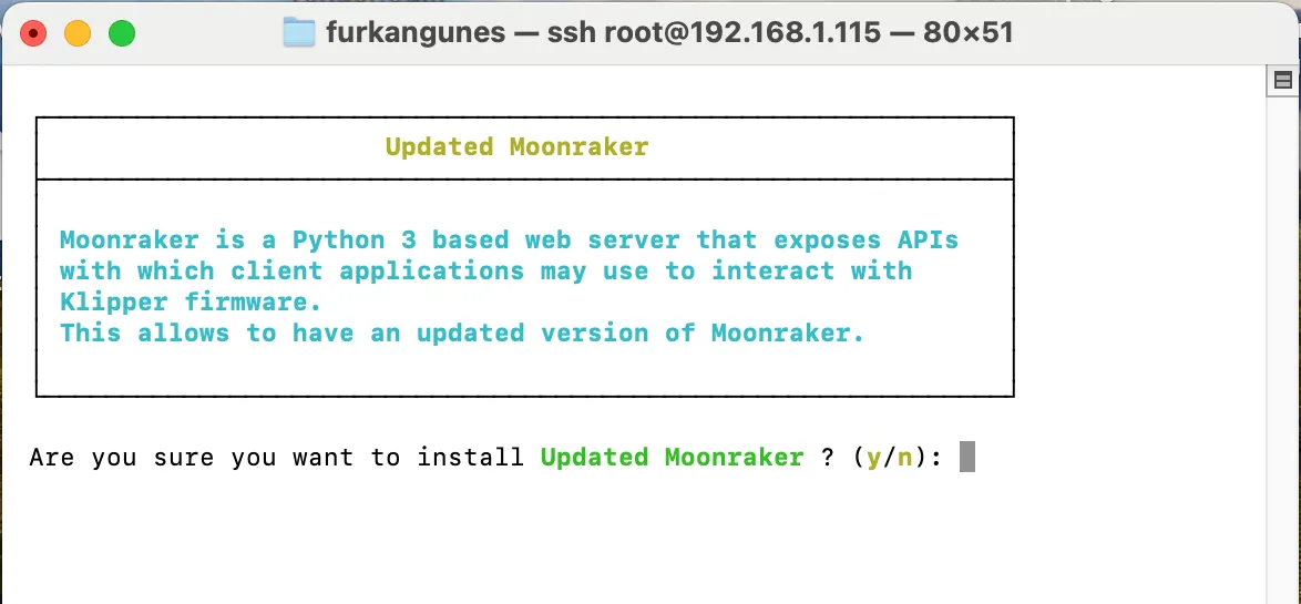
This prompt will ask if you are sure you want to install Moonraker. Type Y to start the process. Once Moonraker is successfully installed or updated, you will see the following screen:
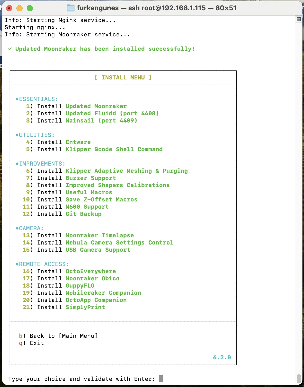
As the second step, type 3 and press the Enter key to install Mainsail.
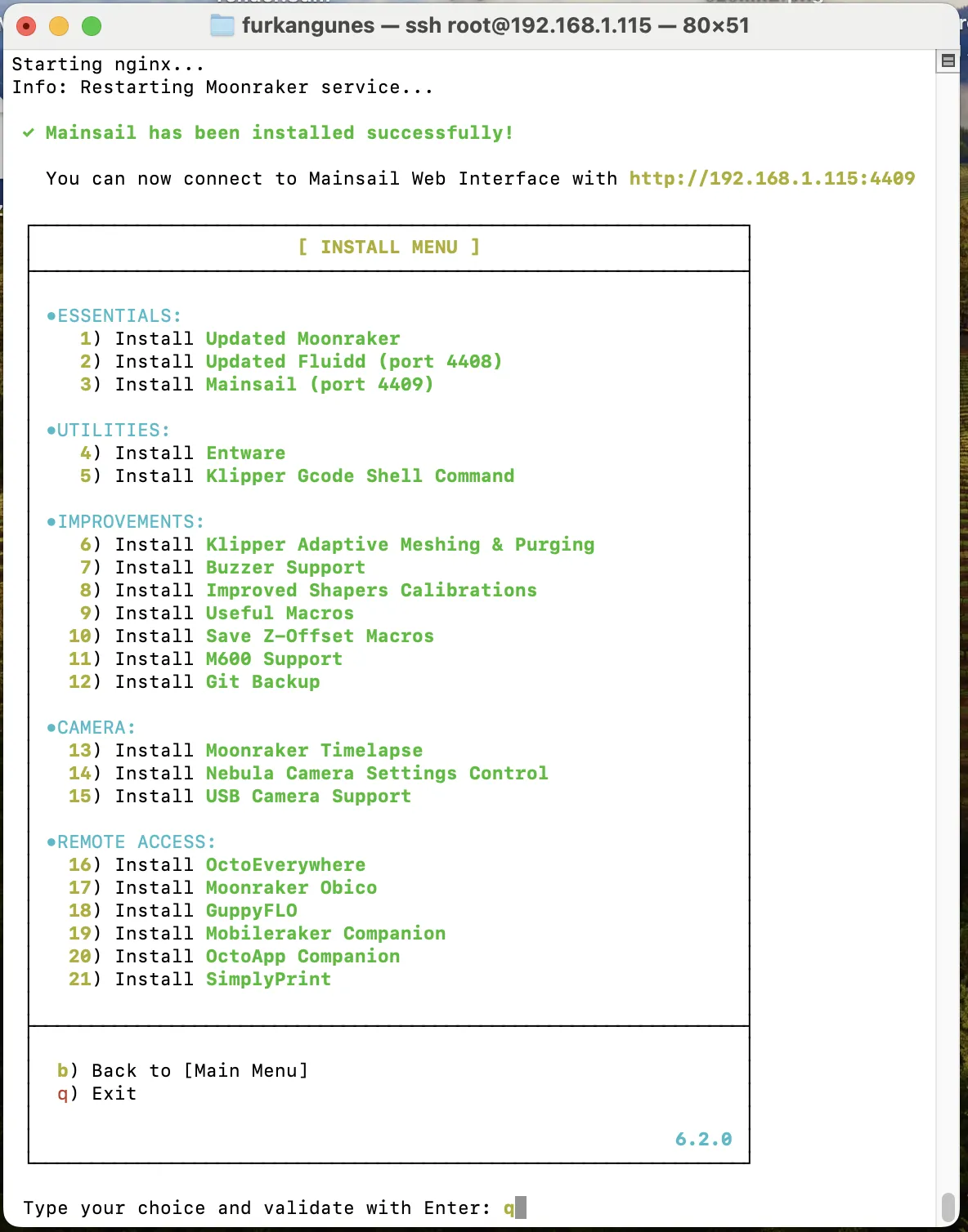
All installations have been successfully completed. Now, type q to exit the helper program and return to the terminal.
¶ Download the Klipper
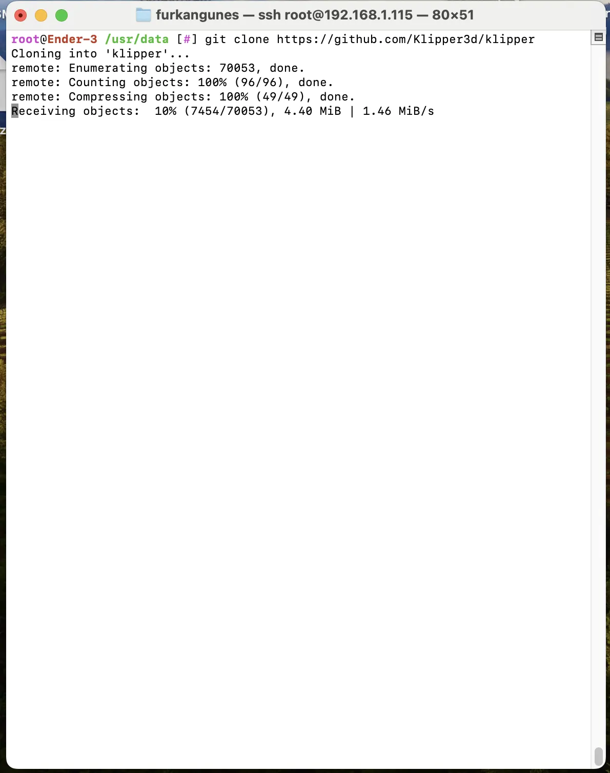
Run the command git clone https://github.com/Klipper3d/klipper to download Klipper.
¶ Navigate to the Klipper file location
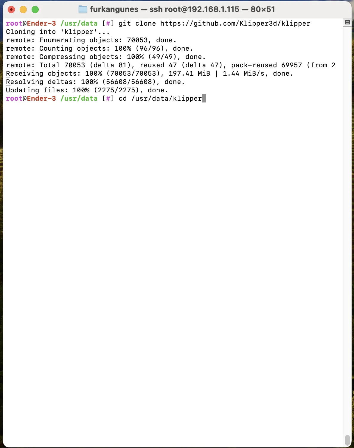
Run the command cd /usr/data/klipper to navigate to the file location.
¶ Run the command
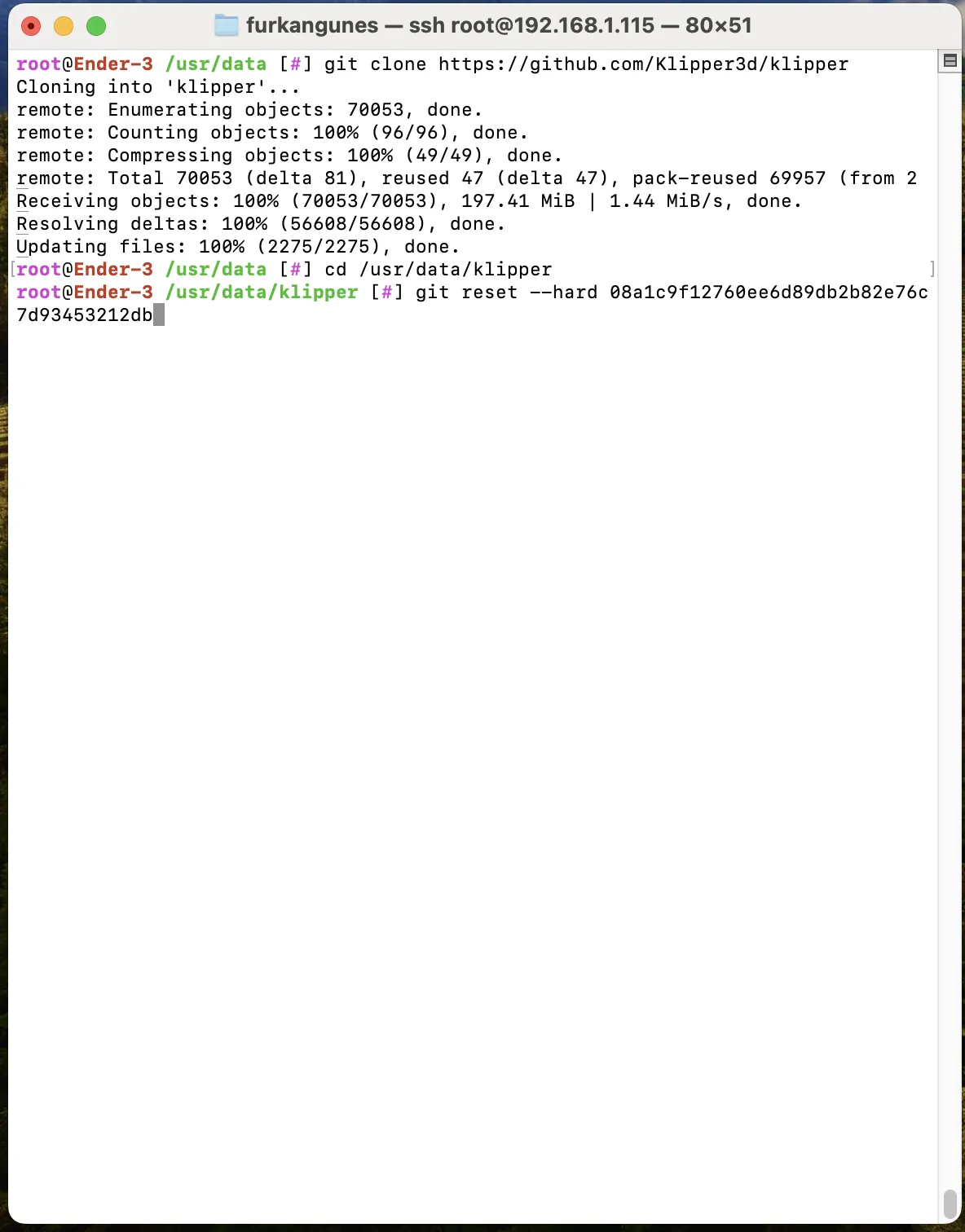
Run the command:
git reset --hard 08a1c9f12760ee6d89db2b82e76c7d93453212db
¶ Access the Mainsail interface to upload the file
First, download the klippy.tar.gz file by clicking on the link. Do not extract the downloaded file. Instead, access the Mainsail interface, click on the 'Machine' tab, and upload the file directly from the file manager located there.
To access Mainsail, use your printer's IP address along with the Mainsail port, which is :4409. For example, paste 192.168.1.115:4409 into your browser to open Mainsail and navigate to the 'Machine' section.
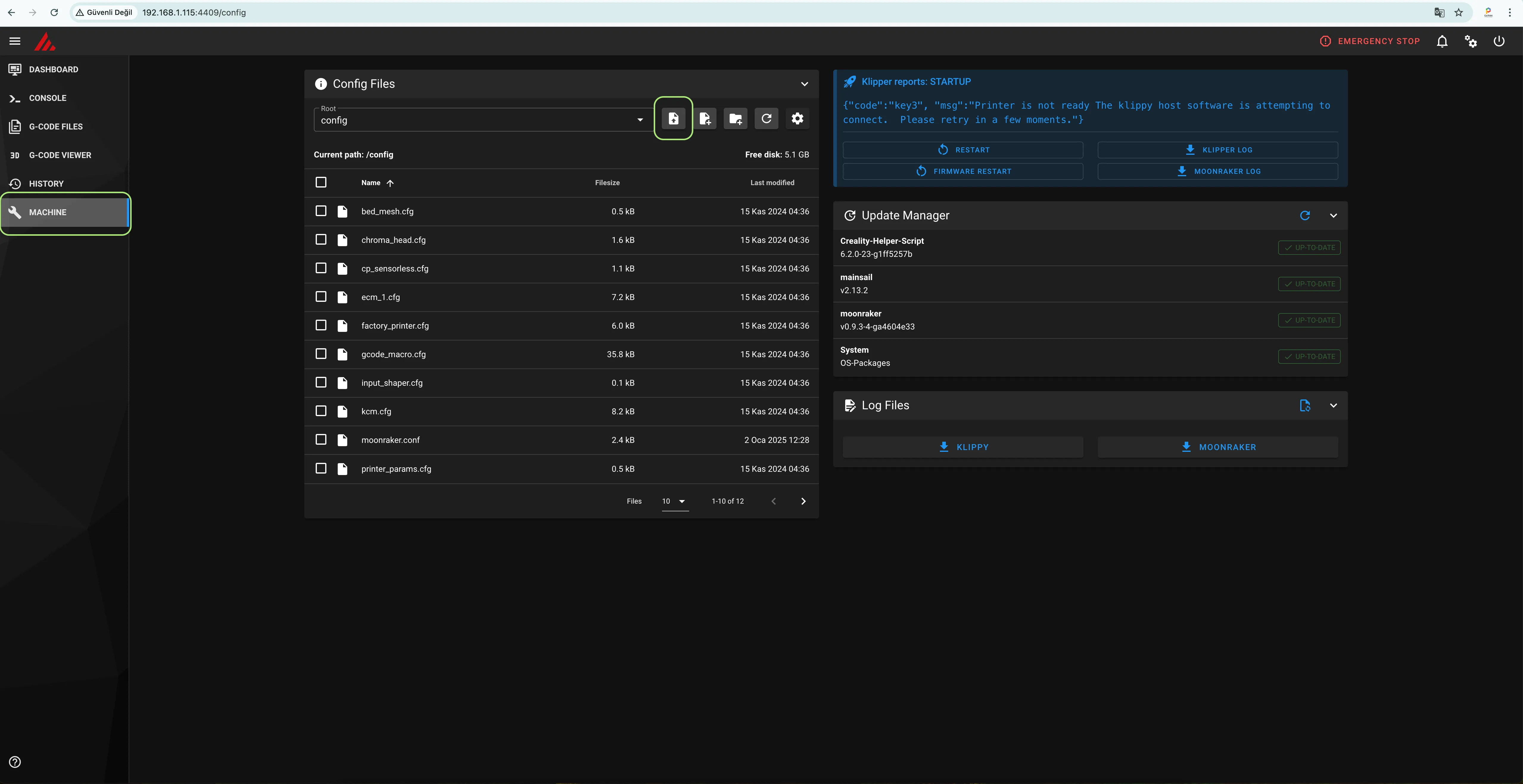
Select the [klippy.tar.gz] file located on your computer and click 'Upload'.
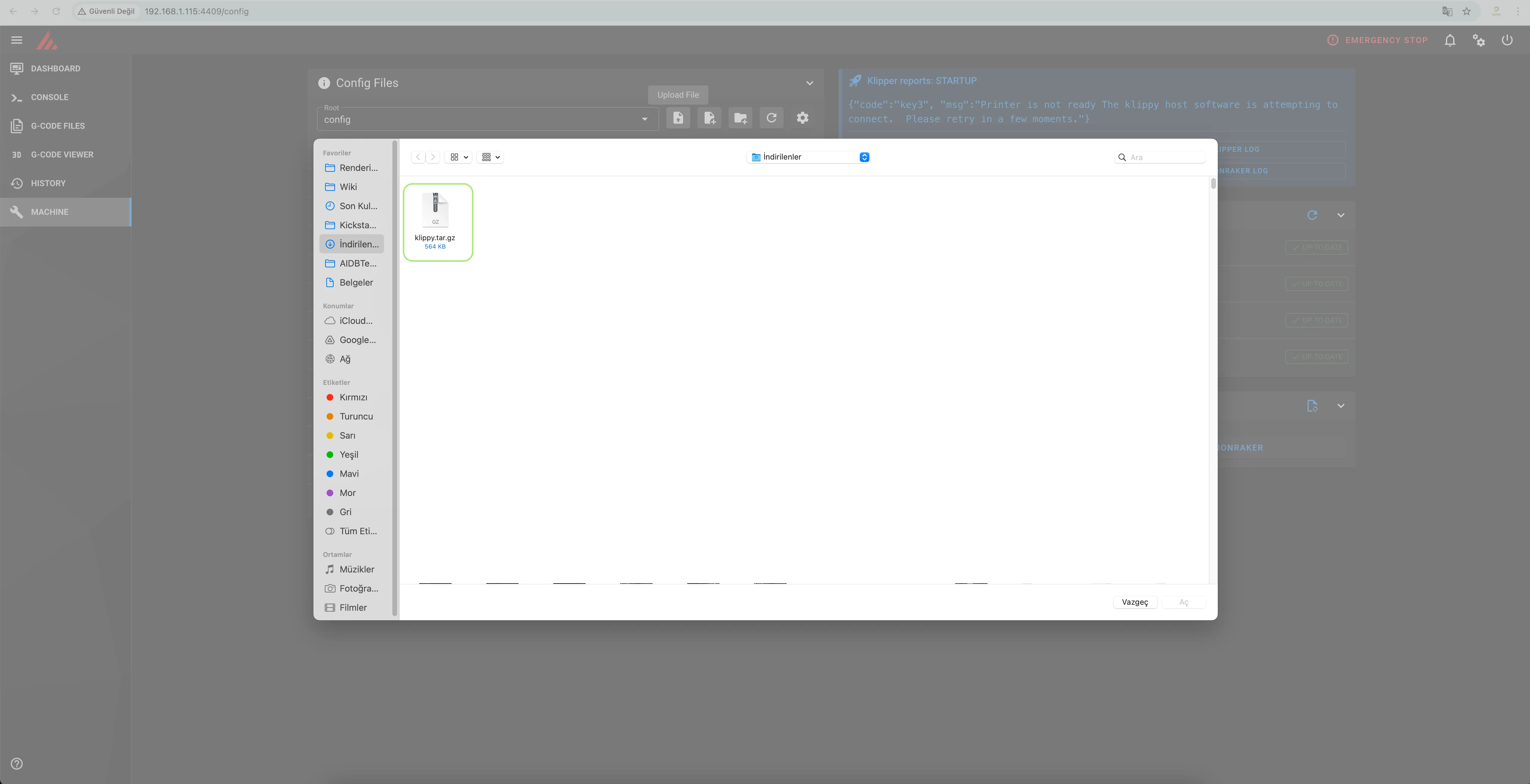
Once the process is complete, return to the terminal.
¶ Run the command
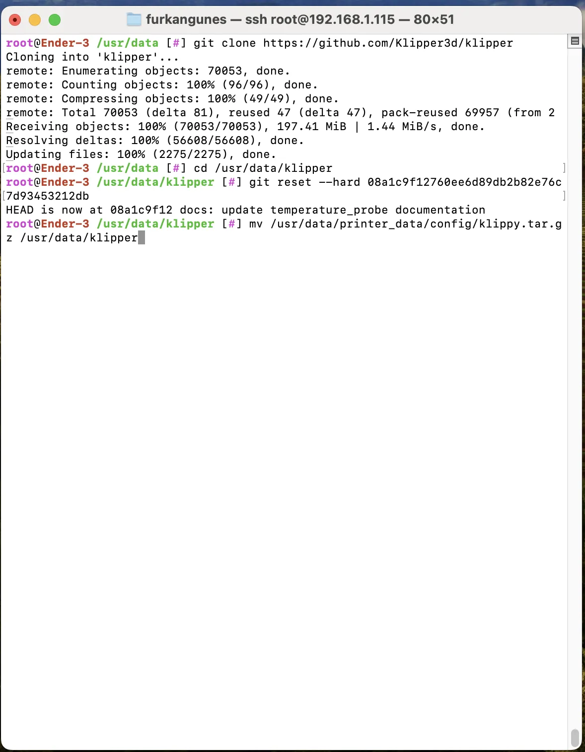
Run the command: mv /usr/data/printer_data/config/klippy.tar.gz /usr/data/klipper
¶ Extract the compressed file using the command
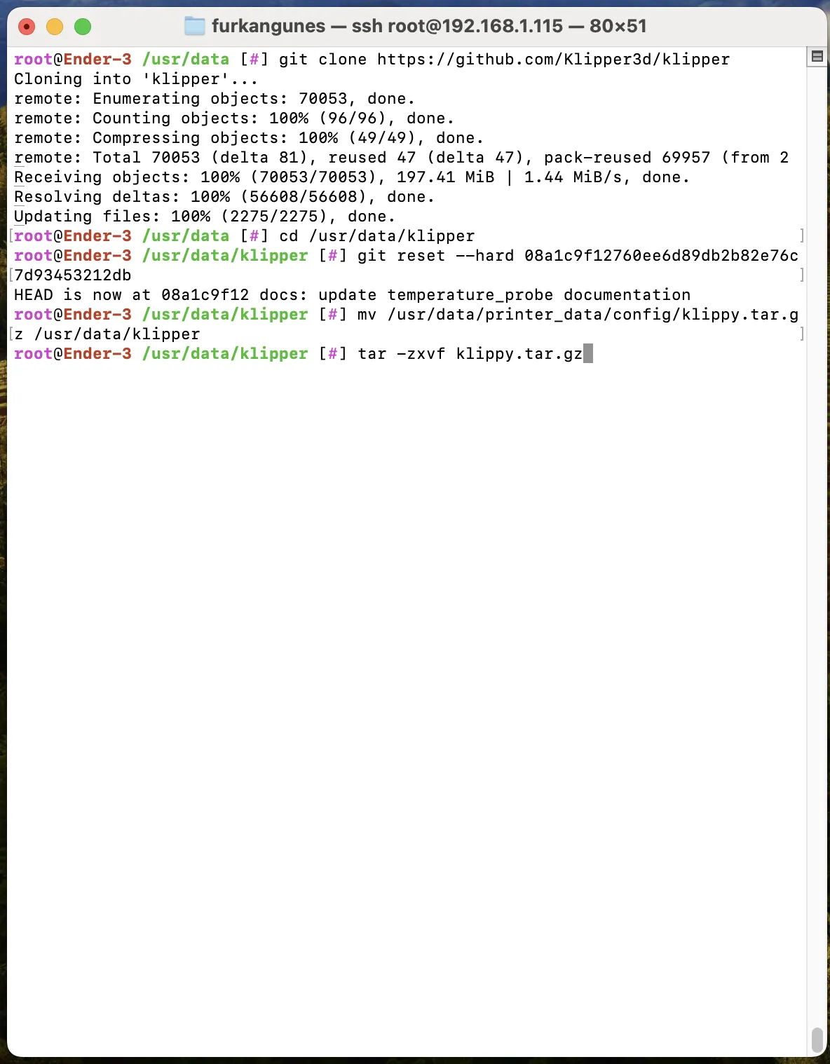
Run the command:tar -zxvf klippy.tar.gz
¶ Edit the file
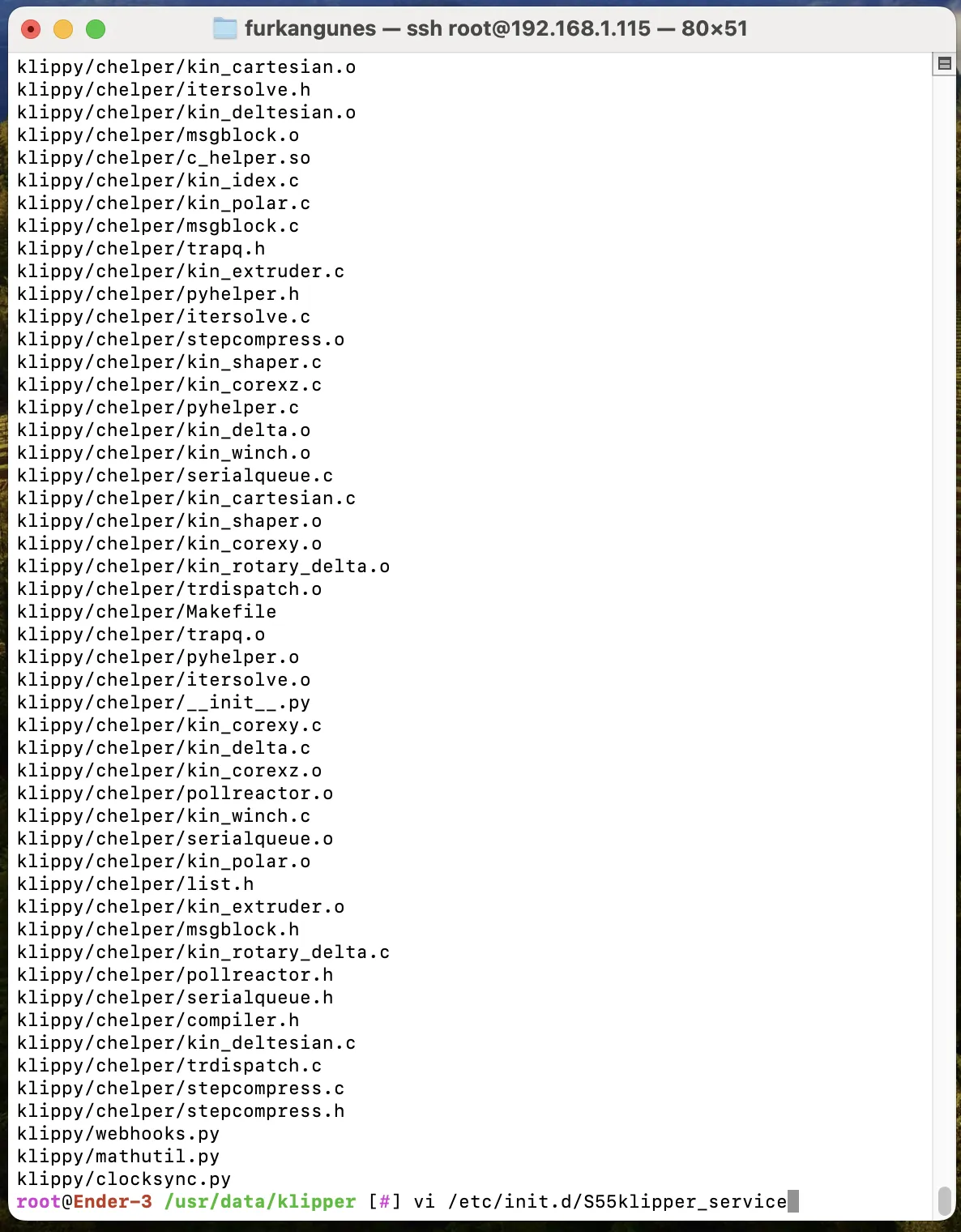
Run the command: vi /etc/init.d/S55klipper_service
¶ Edit the file
First, if you cannot edit the file, press the i key to enter edit mode.
Locate the line:
PY_SCRIPT=/usr/share/klipper/klippy/klippy.py
Comment out this line by adding a # at the beginning, turning it into a comment.
Then, copy the line below it.
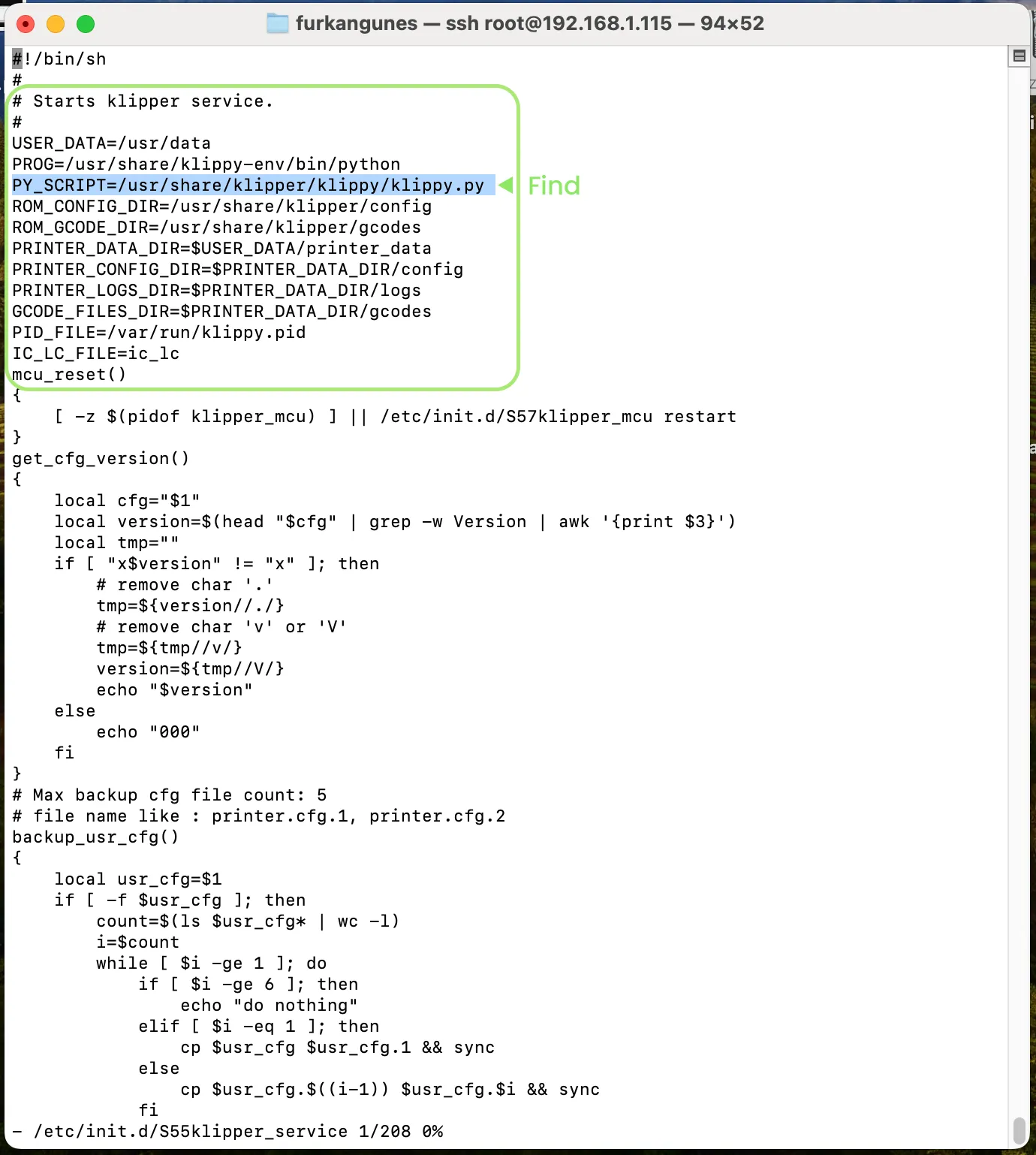
The line you copied should not have a # at the beginning. Replace the share part with data, making the line look like this:
PY_SCRIPT=/usr/data/klipper/klippy/klippy.py

Scroll down in the file to locate the line containing copy_config(). Change it to:
#copy_config()
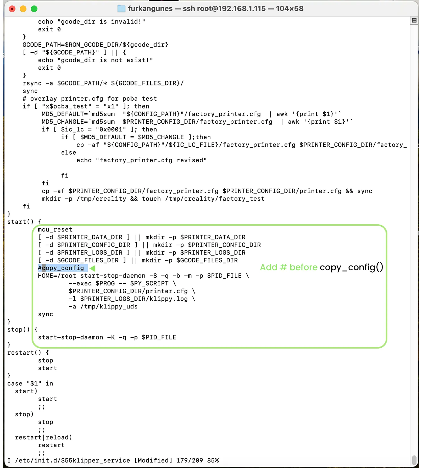
After editing is finished, press the ESC button on the keyboard to exit edit mode. Then, type :wq and press Enter to save and close the file.
¶ Restart the Klipper system
Use the command:
/etc/init.d/S55klipper_service restart
to restart the system.
The steps are now complete. Finally, we will upload the configuration files through Mainsail.
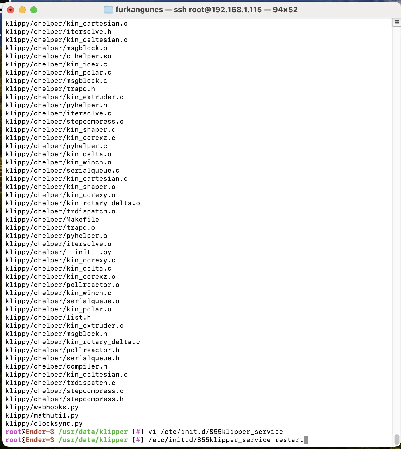
¶ Uploading Configuration Files via Mainsail
Access the Mainsail interface by entering your printer's IP address followed by :4409 in your browser. For example, the address will be 192.168.1.115:4409 Copy this address into your browser and log in to Mainsail.
Go to the 'Machine' section. Click on the upload button located in this section and select the configuration files you previously downloaded to your computer. Upload these files to the system.
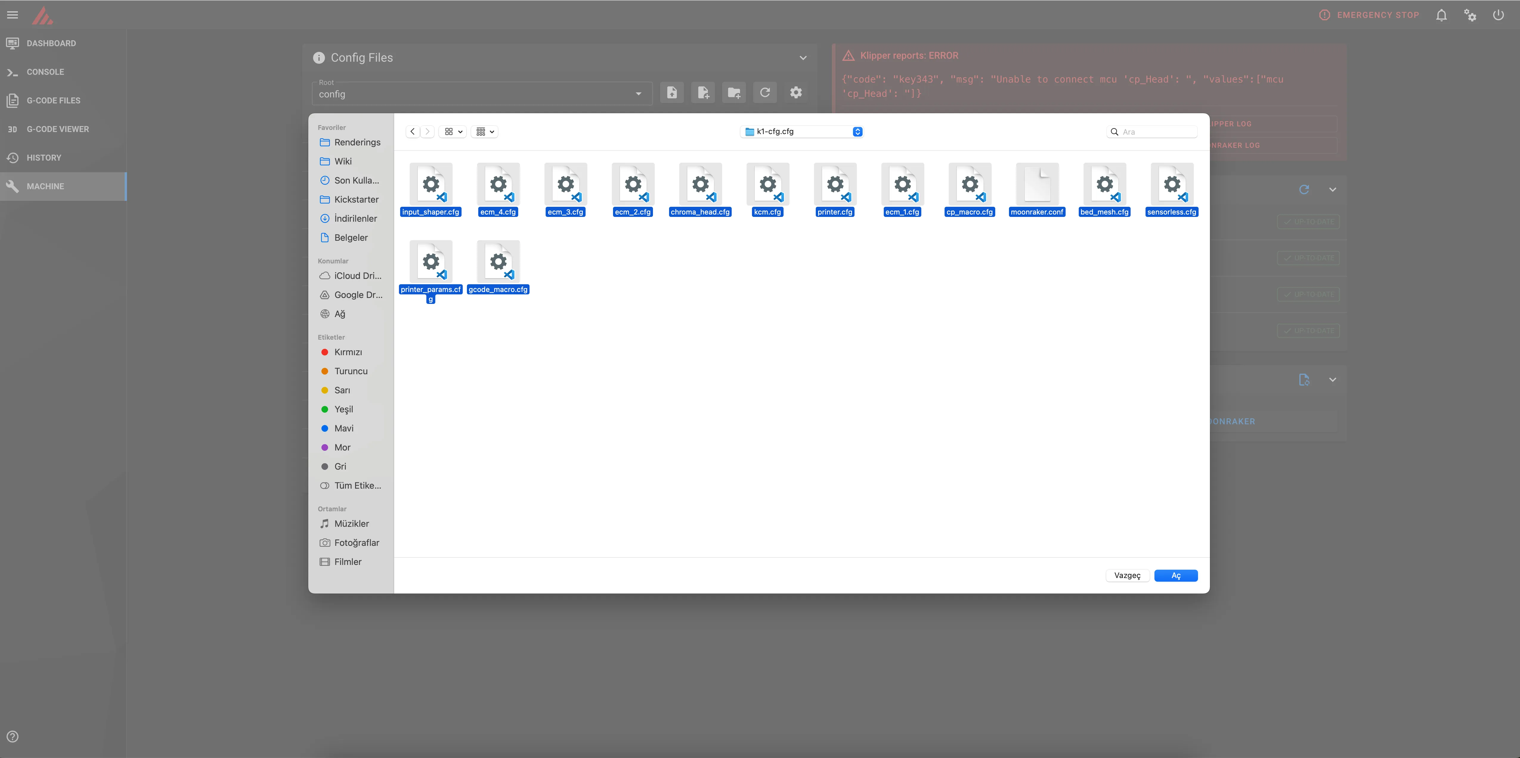
¶ Setting Up MCU Paths
f you plan to use the system with 4 colors and connect the KCM cable directly to your K1 device, there is no need to configure the MCU paths. However, if you are using a USB hub or connecting an ECM, you will need to set up the USB paths.
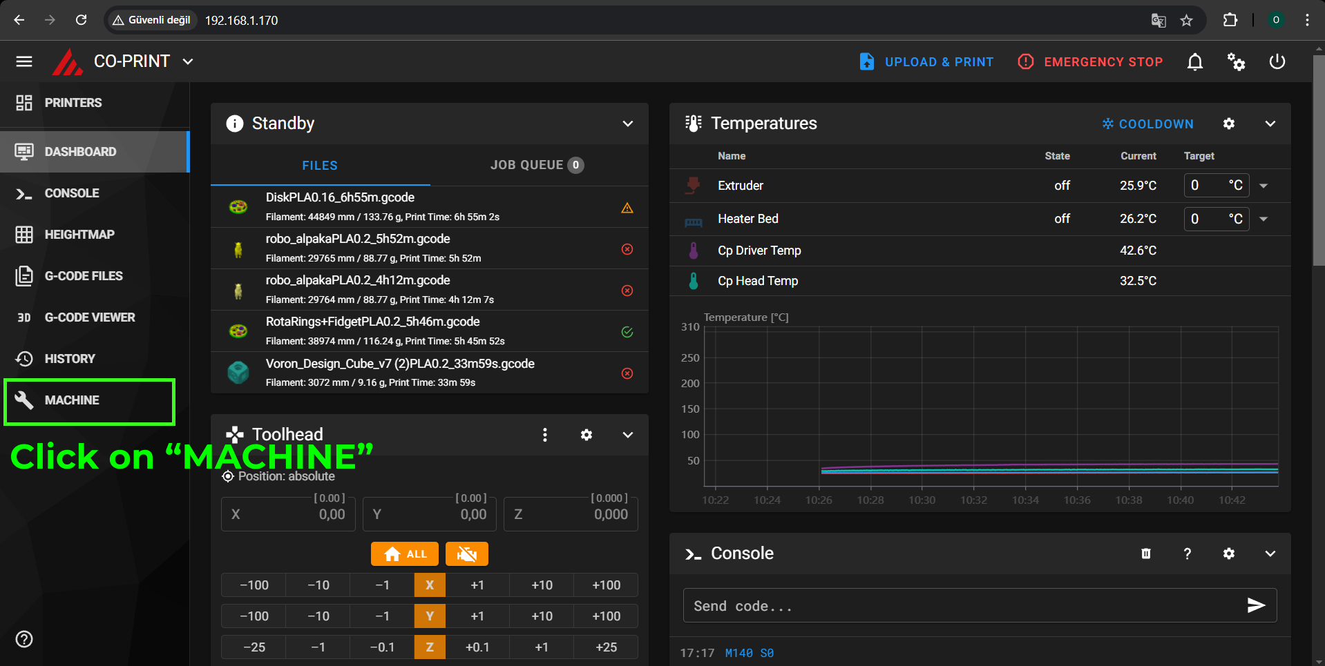
¶ 1- Go to Mainsail and navigate to the Machine section
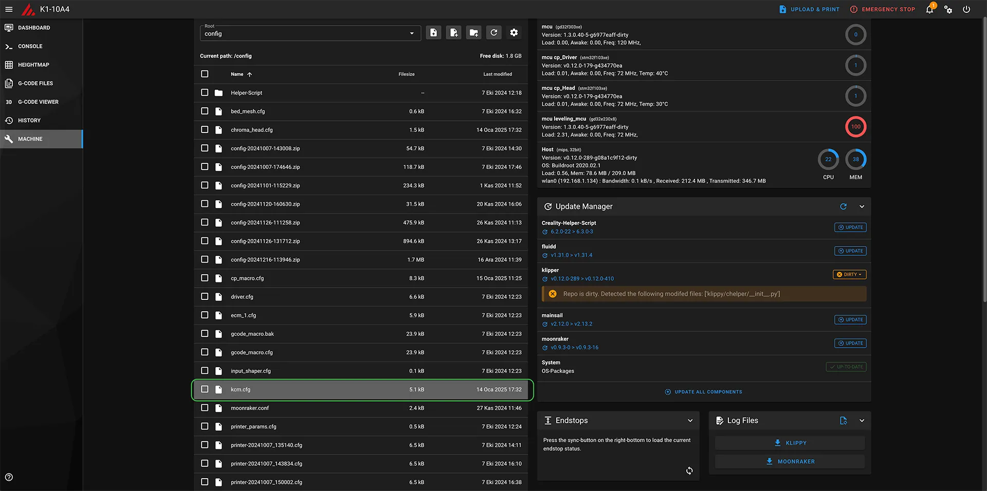
¶ 2- Locate kcm.cfg and open it in the editor.
Locate the KCM.CFG file, one of the configuration files we uploaded to the Machine section, and click on it to open it in the editor.
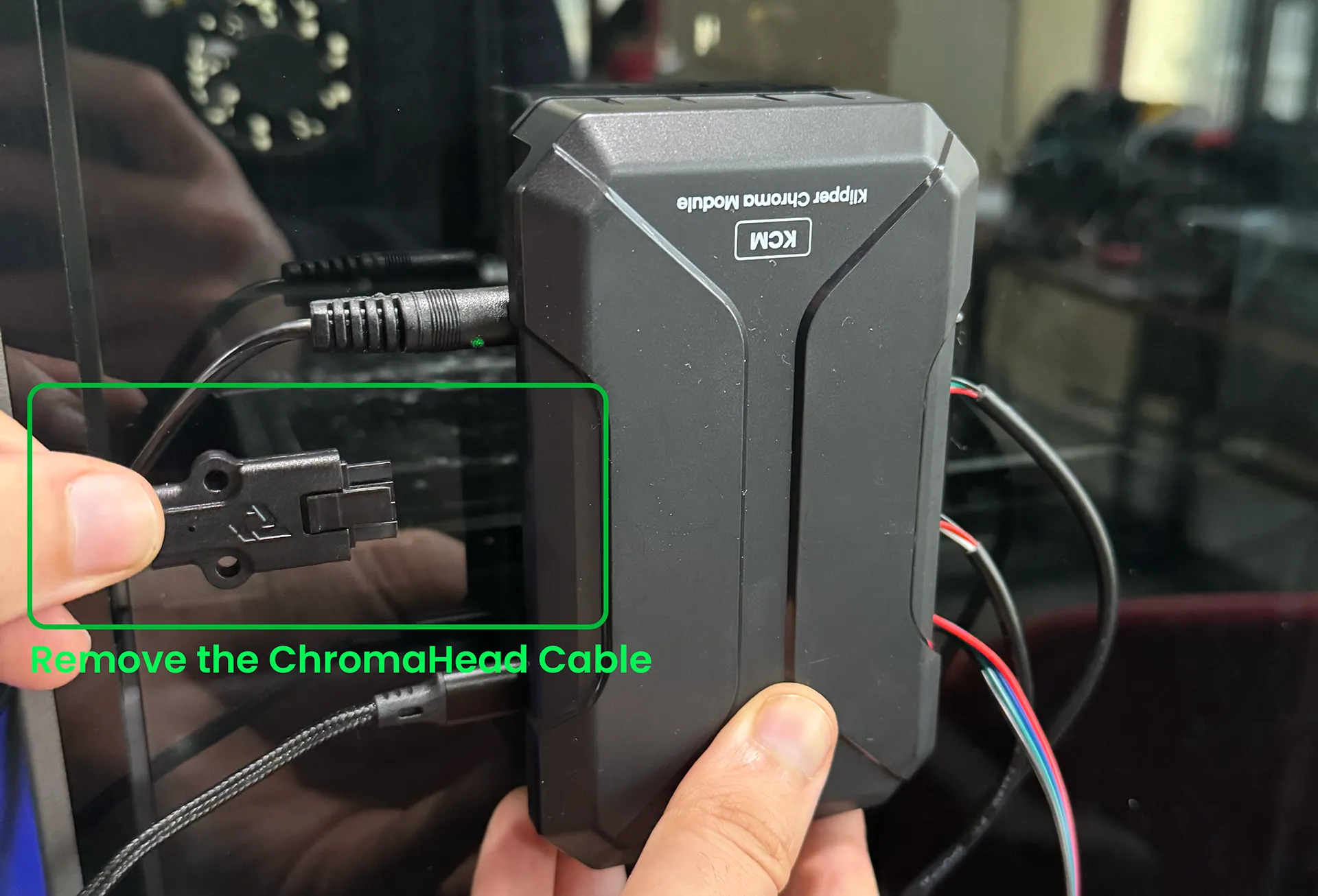
¶ 3- Unplug the ChromaHead cable from the KCM
Unplug the ChromaHead cable from the KCM while the KCM's USB cable is connected to the 3D printer.
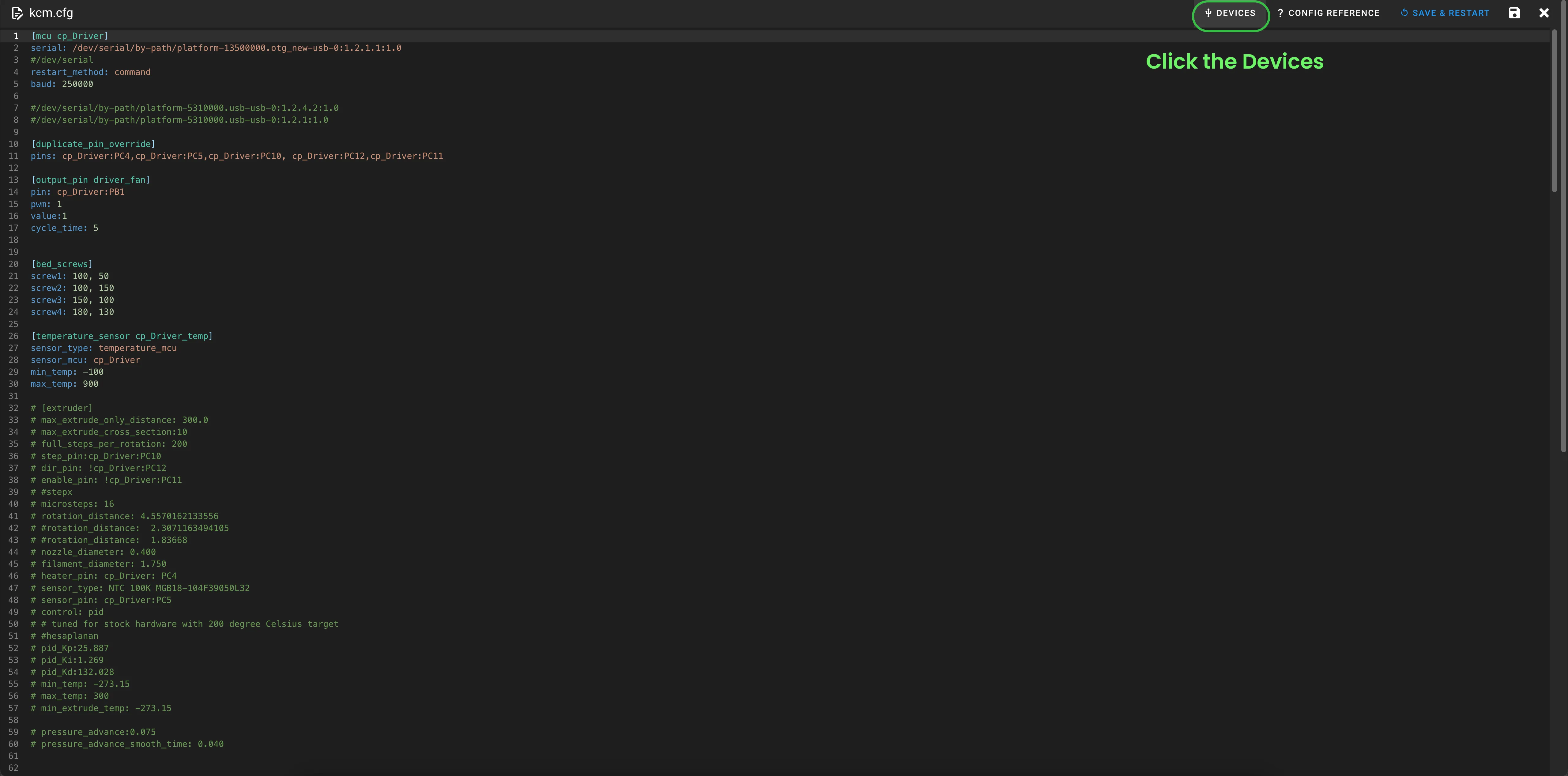
¶ 4- Open the devices section within the KCM.cfg file
Click the devices button located in the top-right corner of the KCM configuration file.
¶ 5- Click the Refresh button
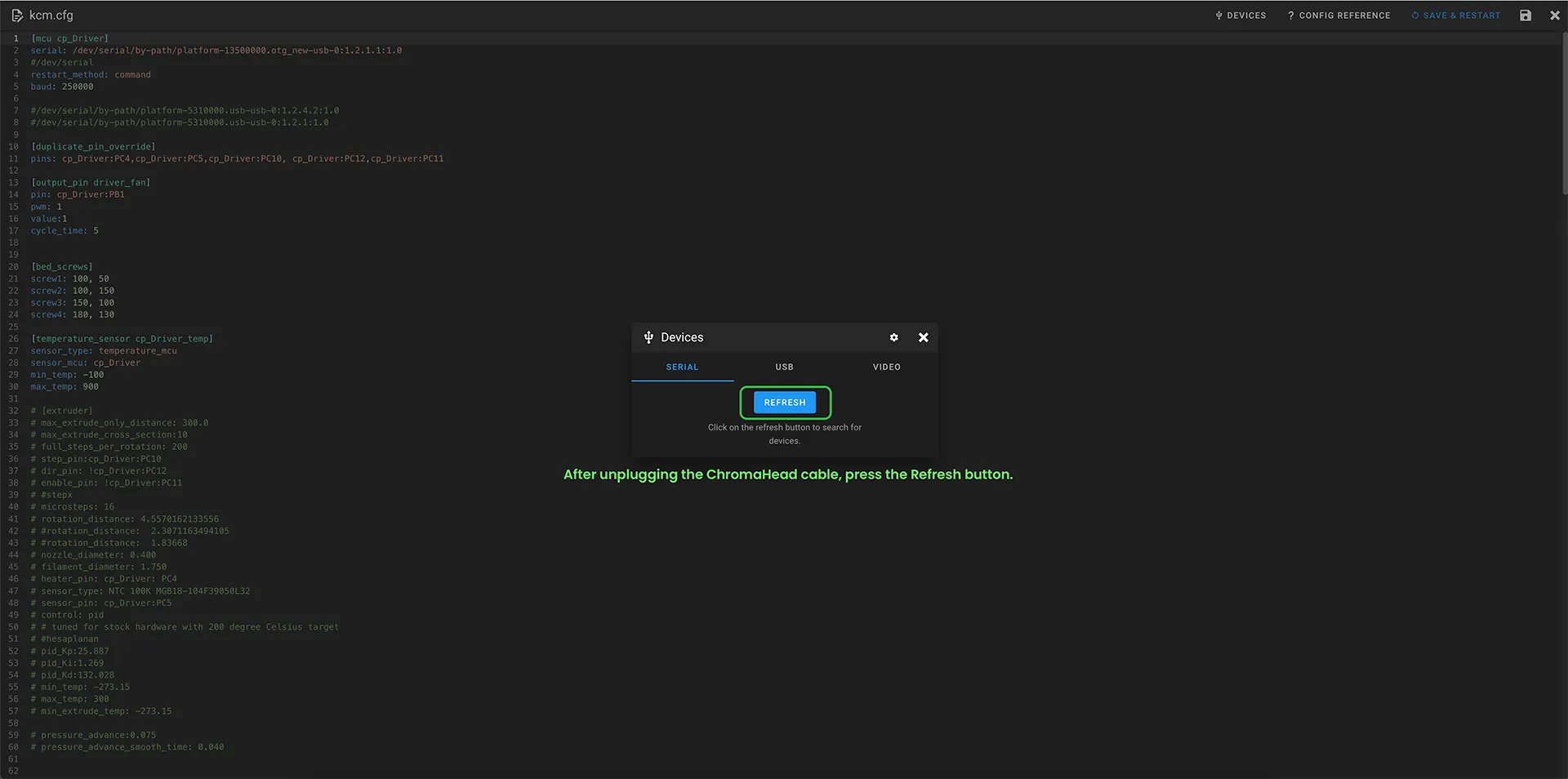
In the Devices section, click the Refresh button under the Serial tab. Make sure you have unplugged the ChromaHead cable before doing this.
¶ 6- Copy the USB path
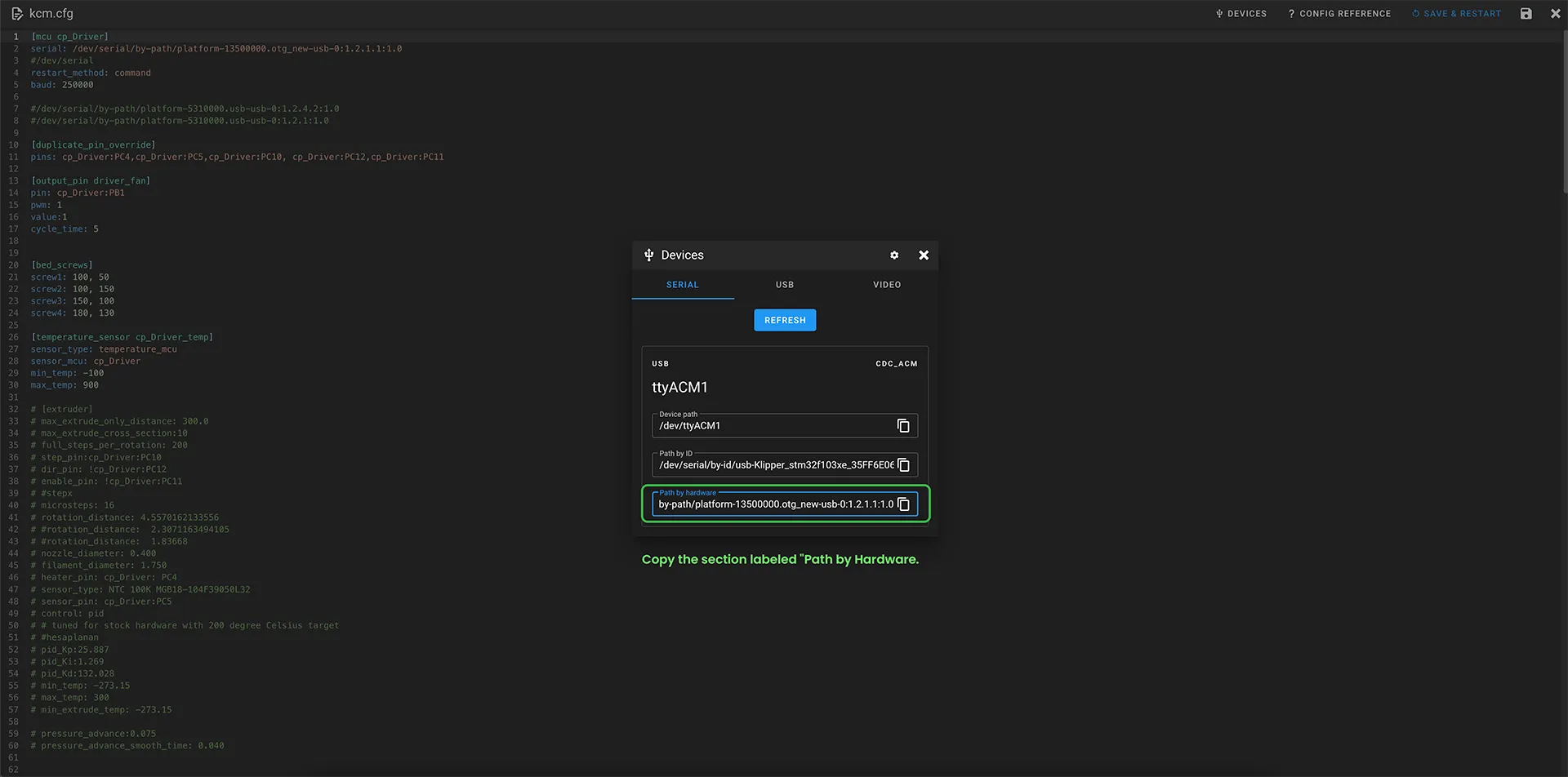
When you click the Refresh button, only one device will appear. Copy the Path by Hardware listed under the Serial tab for this device. Additionally, remember the last three digits of this path, for example, 1:1.0.
¶ 7- Paste the USB path onto the KCM configuration
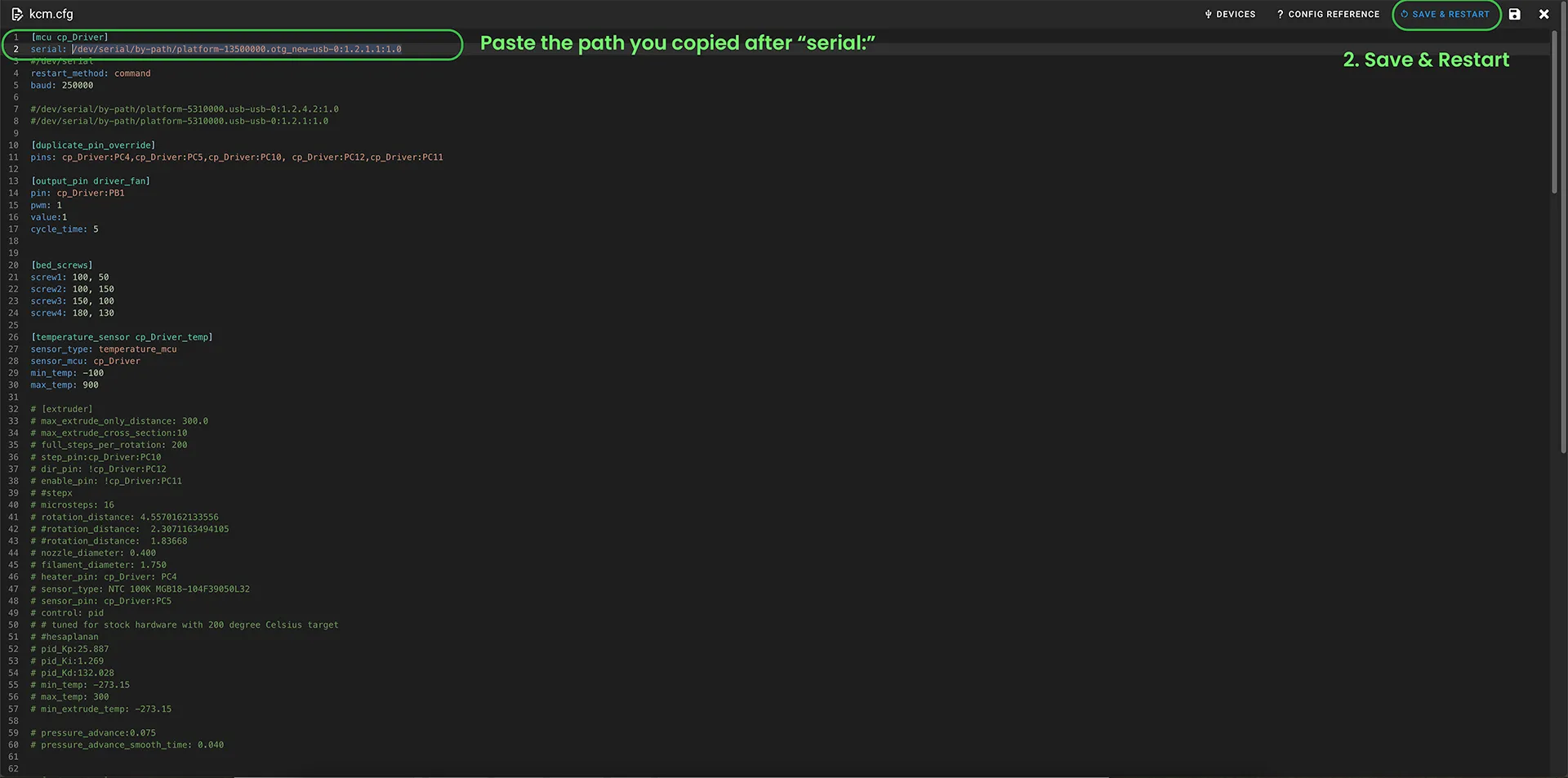
Close the Devices section and paste the copied path into the serial: field located right below [mcu cp-Driver] at the very beginning of the KCM.cfg file. Then, click the Save & Restart button to save the file and return to the Machine page.
¶ 8- Reconnect the ChromaHead cable to the KCM
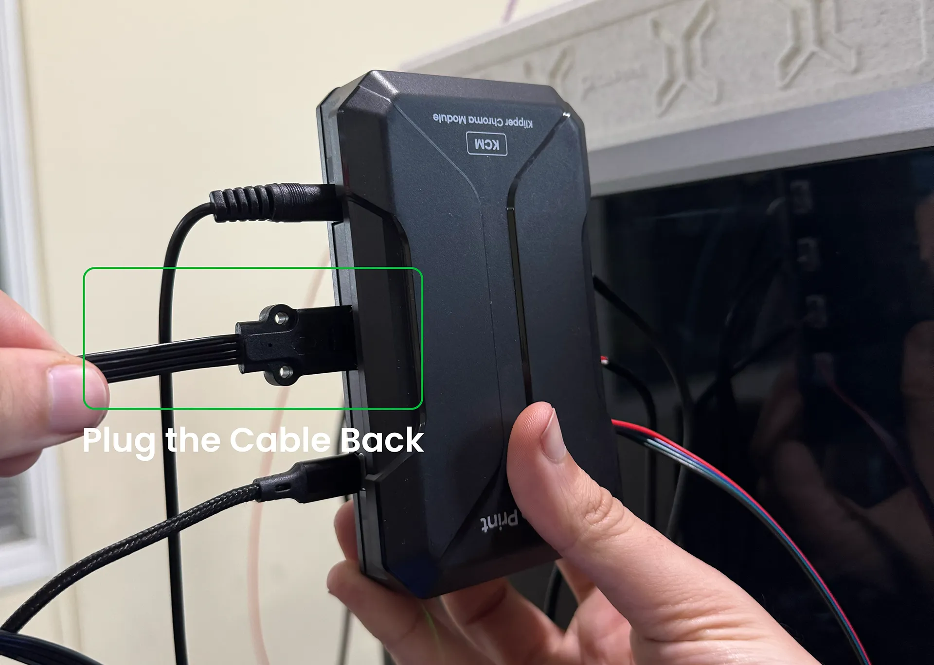
First, reconnect the ChromaHead cable to the KCM to identify its path.
¶ 9- Access the chroma-head.cfg file from the Machine section
Return to the Machine page, locate the chroma-head.cfg file, and open it.
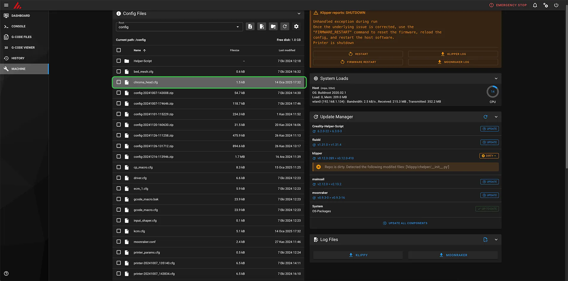
¶ 10- Click on the Devices section and then press the Refresh button
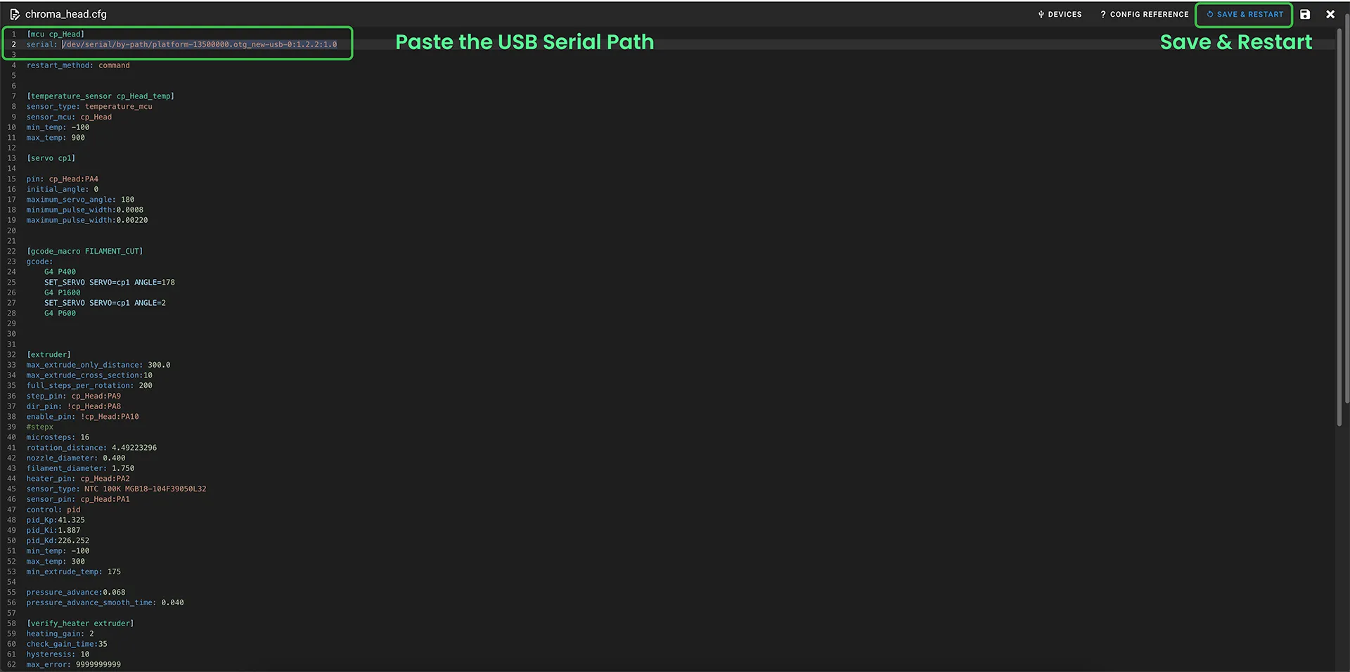
Enter the Devices section and click the Refresh button. Previously, only ttyACM1 was visible, but now you will see ttyACM2 as well. Identify the path that differs from the one you previously pasted, copy the Path by Hardware for this new device, and then exit the Devices section.
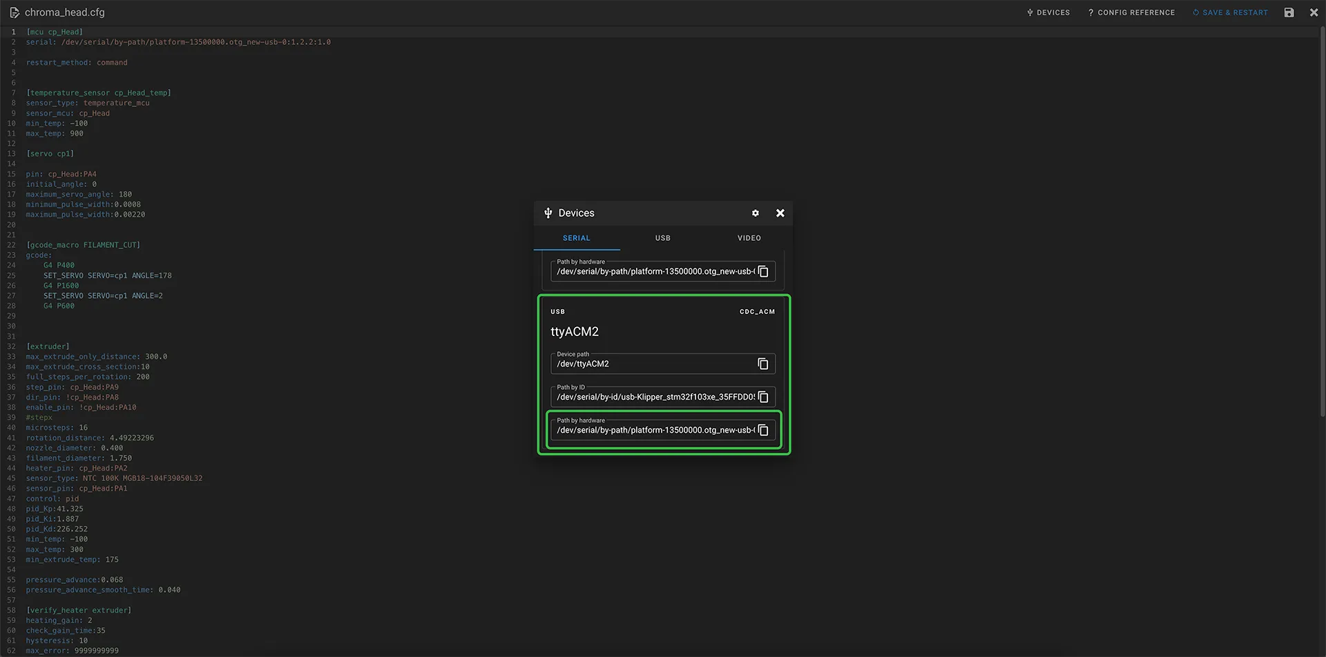
¶ 11- Paste the ChromaHead path into the appropriate field in the chroma-head.cfg file, then save and close the file
At the very beginning of the chroma-head.cfg file, locate the [mcu_co_Head] section. Replace the path following serial: with the newly copied path. Save the file and close it. Your path settings are now complete. After saving and restarting, the connection will be established successfully.
