¶ Welcome to ChromaSet Setup Guide
¶ 1. Connecting ChromaPad to a 3D Printer
Connect ChromaPad to the power source using the power adapter. After connecting to the power source, press the Power button located on the left side.
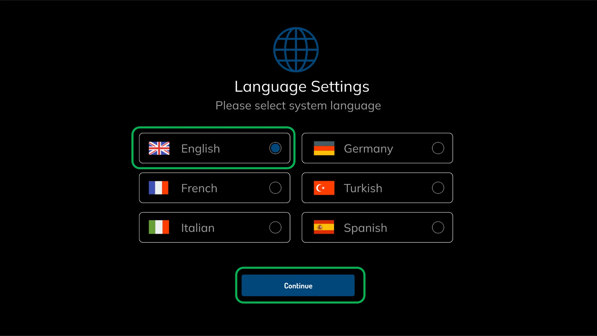
¶ 1.2 Set the System Language
Proceed to the next step by selecting the relevant language from the setup wizard.
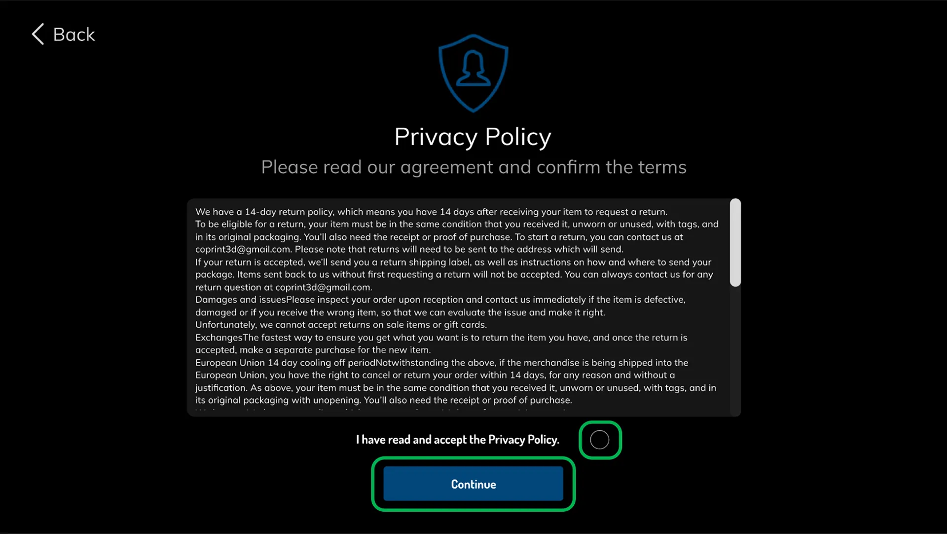
¶ 1.3 Accept the Privacy Agreement
Let's proceed to the next step by agreeing to the Terms of Use and Privacy Policy.
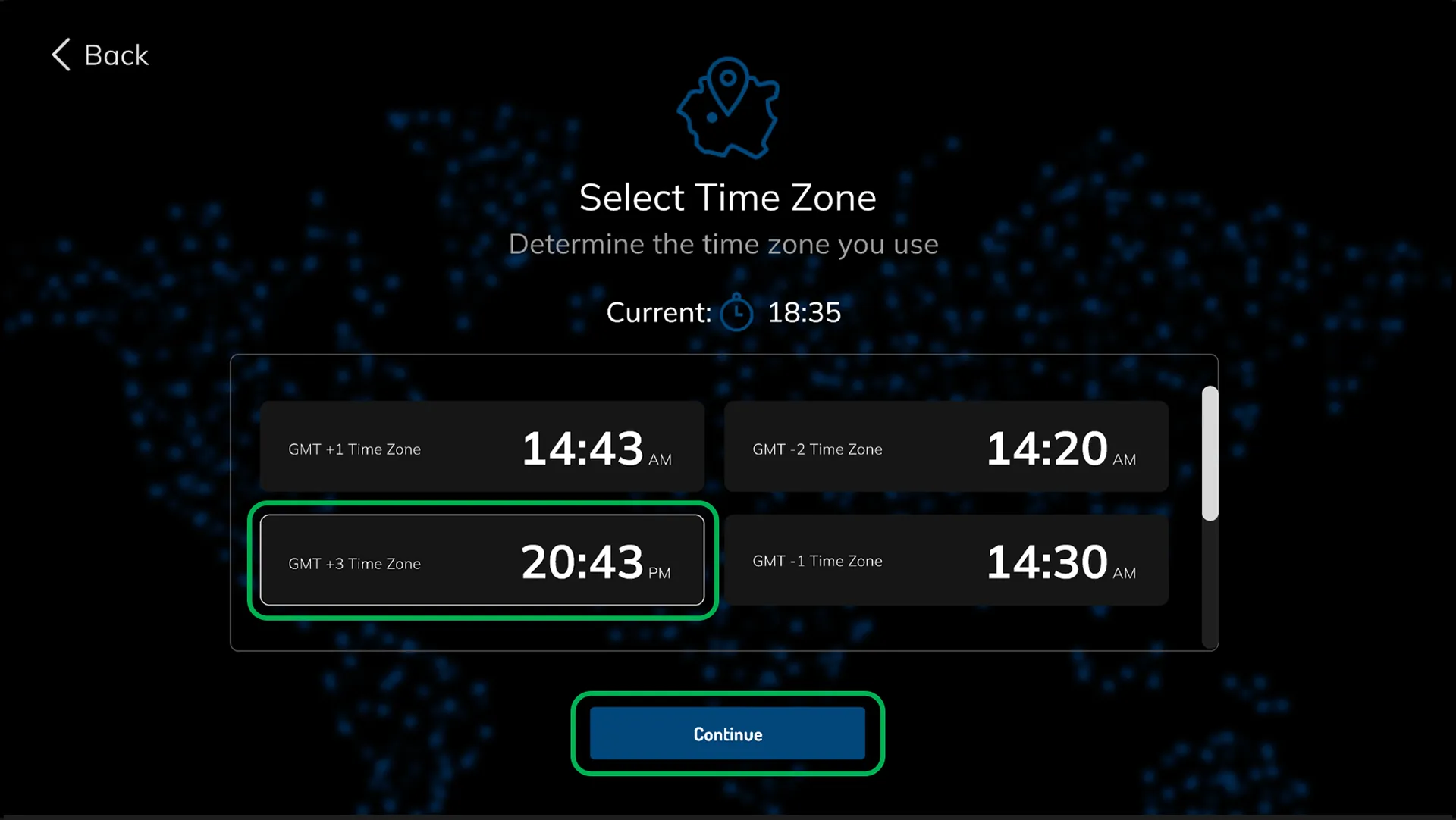
¶ 1.4 Set the Time Zone
Select the GMT code corresponding to your region and adjust your system time according to your location. (All calculations and statistics on the system will be based on the selected time zone.)
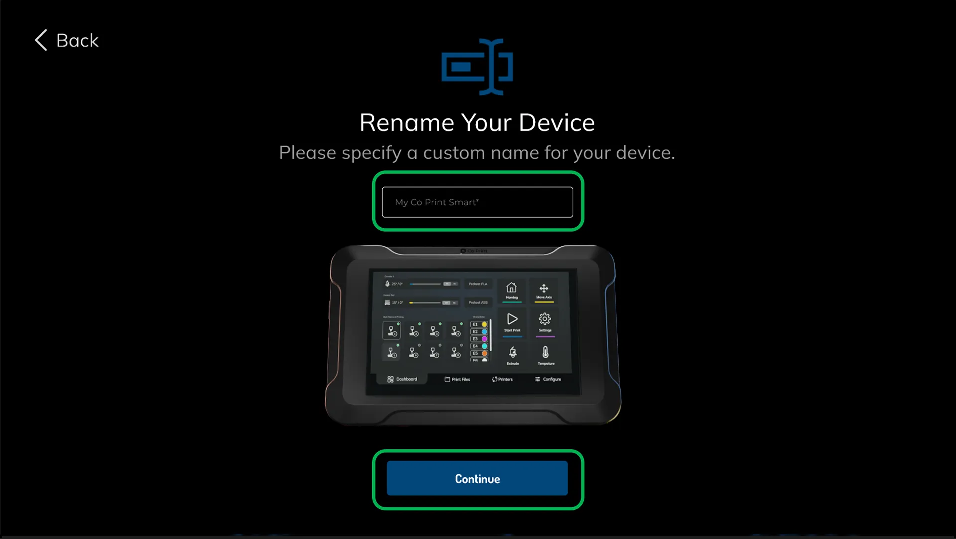
¶ 1.5 Name your ChromaPad
¶ 1.6 Connect to a network
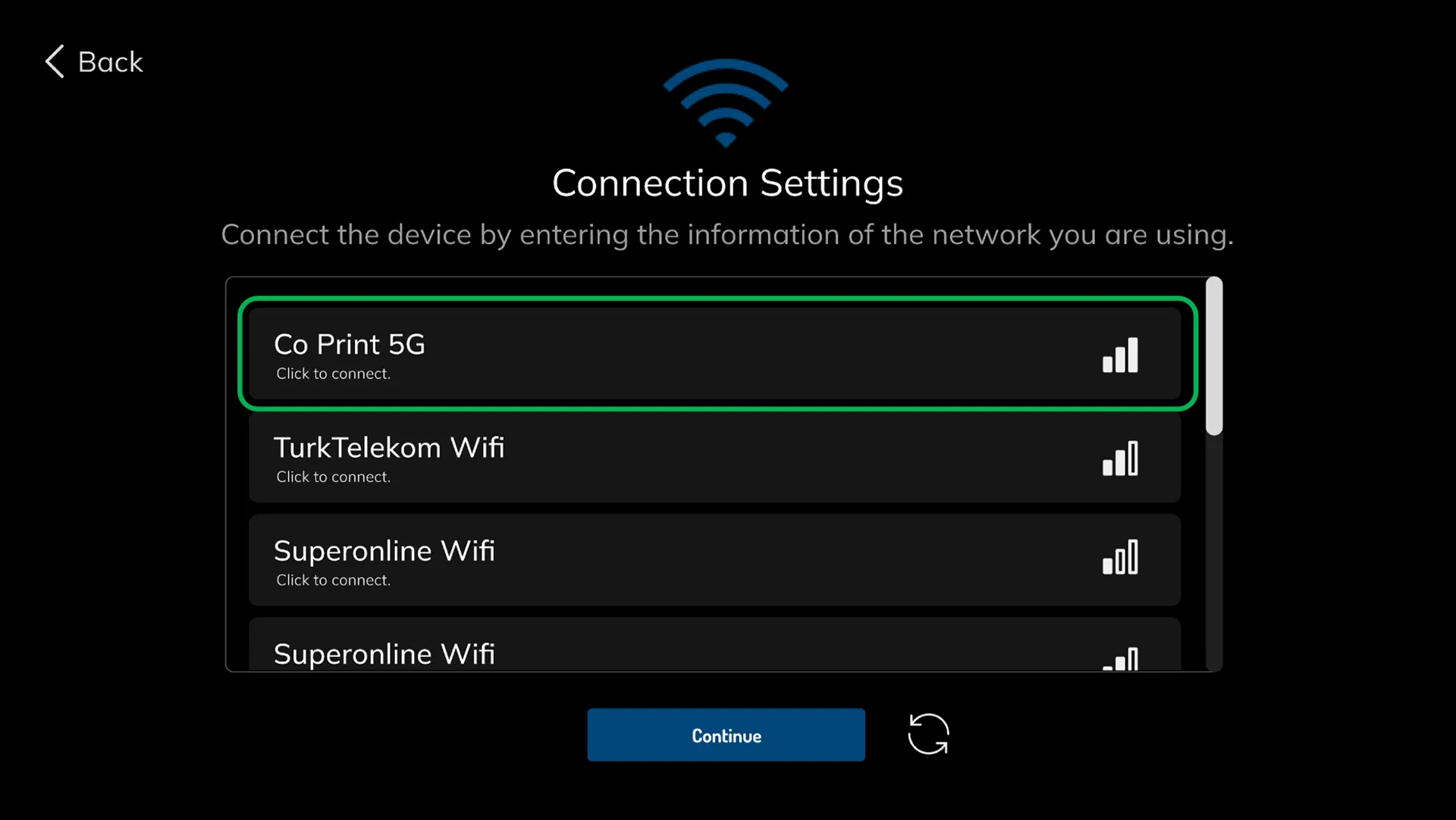
Select your network to connect ChromaPad to the internet, then click on it to connect. If your network is not visible, you can refresh the network list using the refresh button in the top right corner. Enter your network password and wait for the connection to be established. Then, you can proceed.
¶ 1.7 Select your printer
The setup wizard automatically generates the necessary firmware binary file and configuration files specifically tailored for your printer running Klipper. There are presets available for many printers prepared by Co Print. You can use the brand filter in the top left corner to find and select your printer, then proceed.
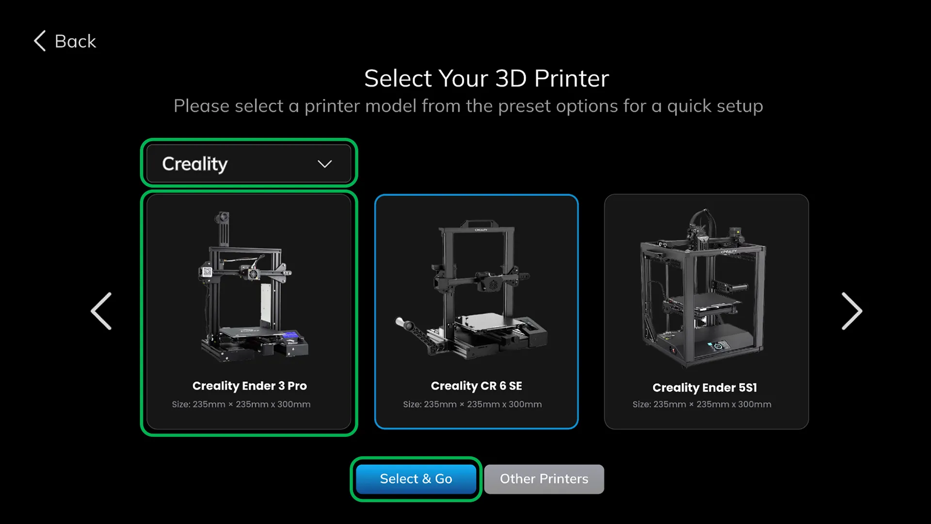
If your printer is listed, you can proceed to the step of writing the binary file.
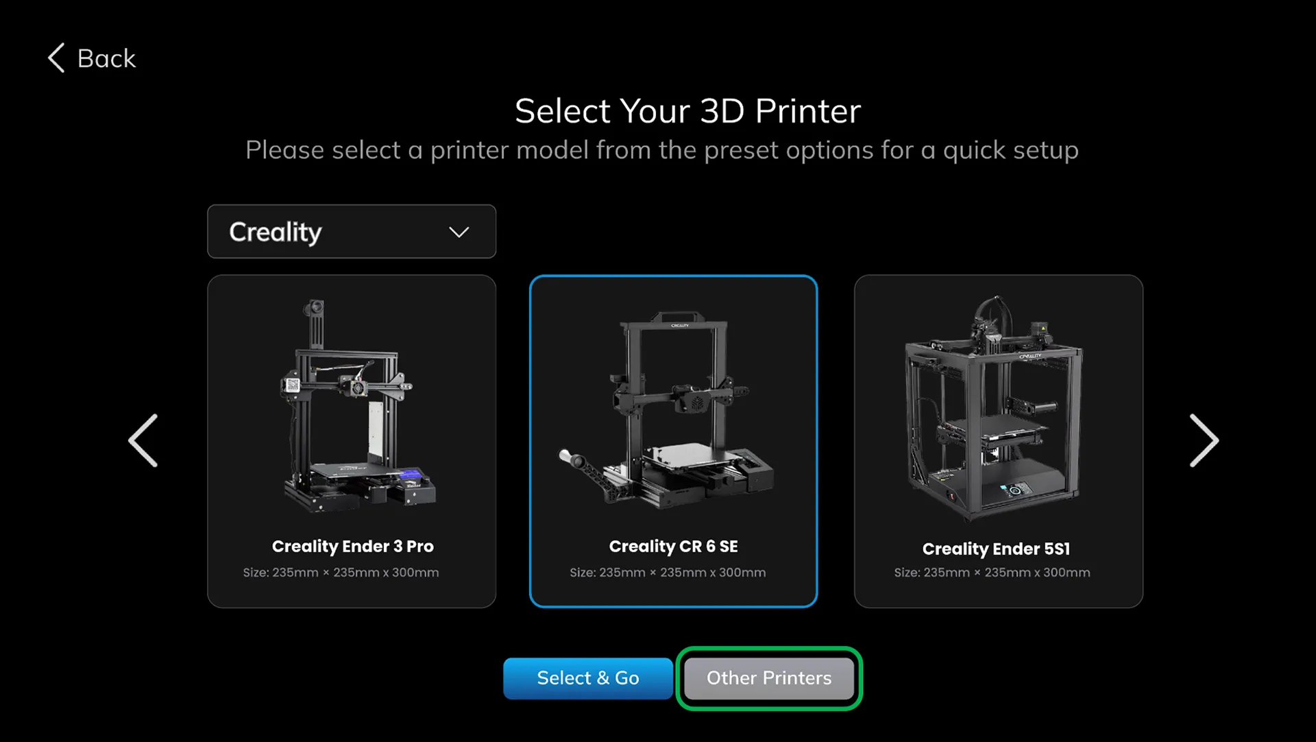
If you can't find your printer in the list, don't worry. You can proceed with the setup by manually selecting the specifications. Click on the "Other Printers" button to continue.
If your printer is an Atmega processor printer, you can get information by clicking on the link.
¶ 1.7.1 Perform Manual Setup
¶ 1.7.2 Select MCU Architecture
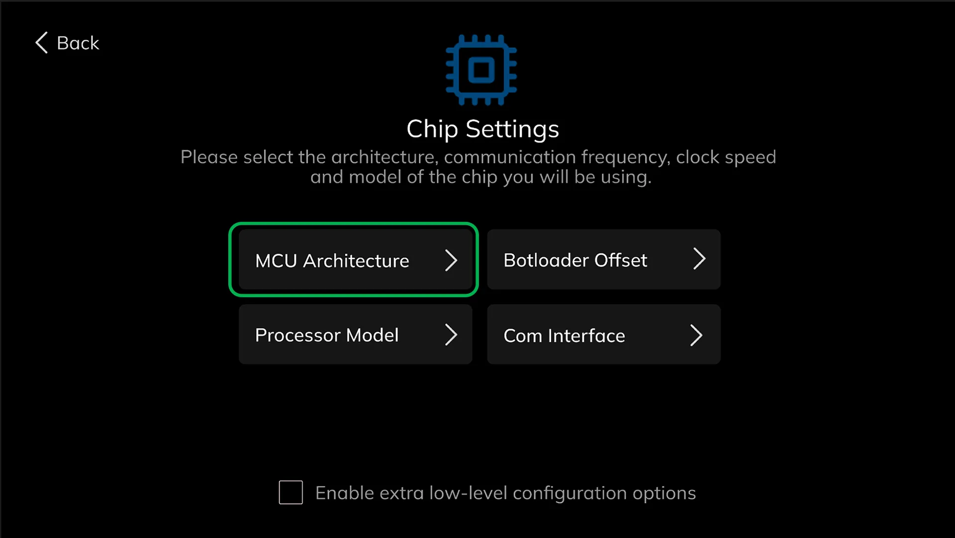
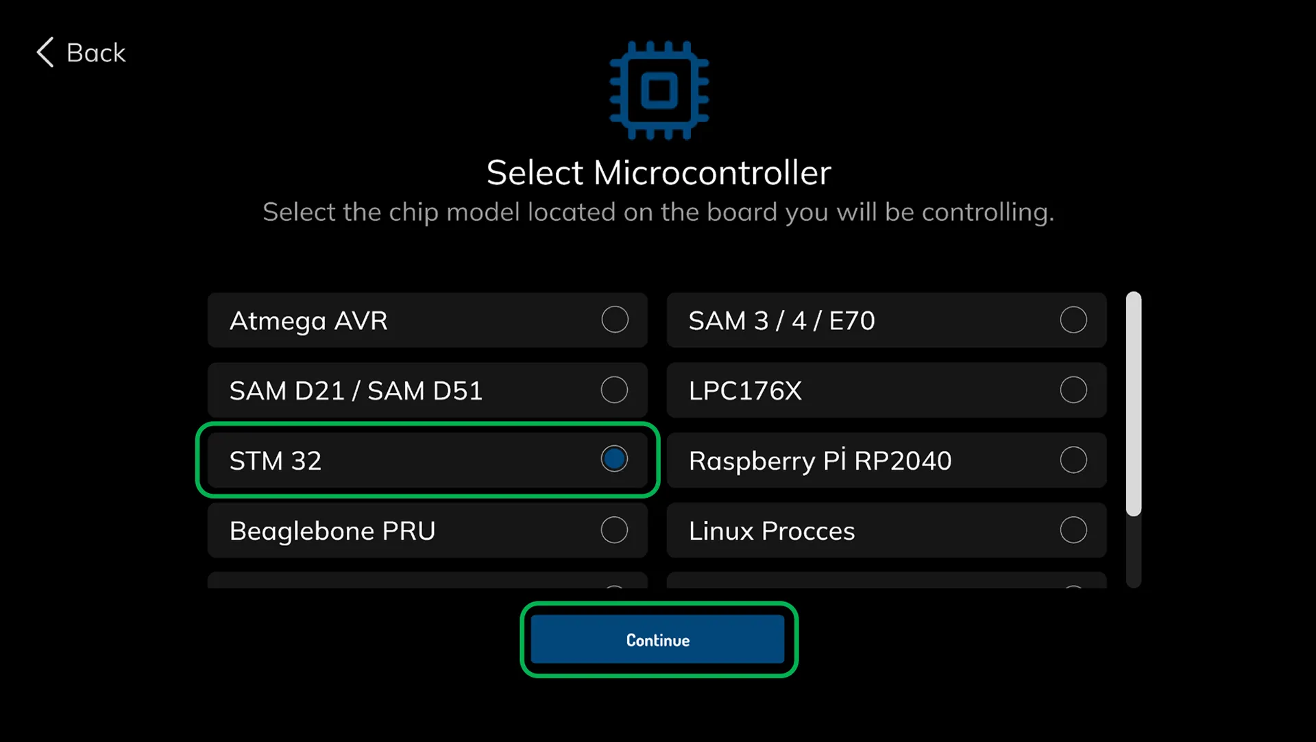
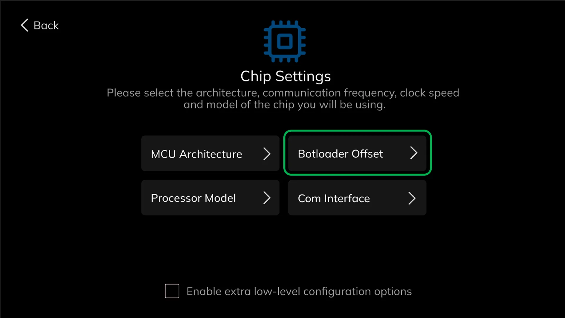
o perform a setup based on the Ender 3 V2 printer, first, you need to select the processor architecture. Click on the "MCU Architecture" button to select the processor architecture.
¶ 1.7.3 Select the MCU Model
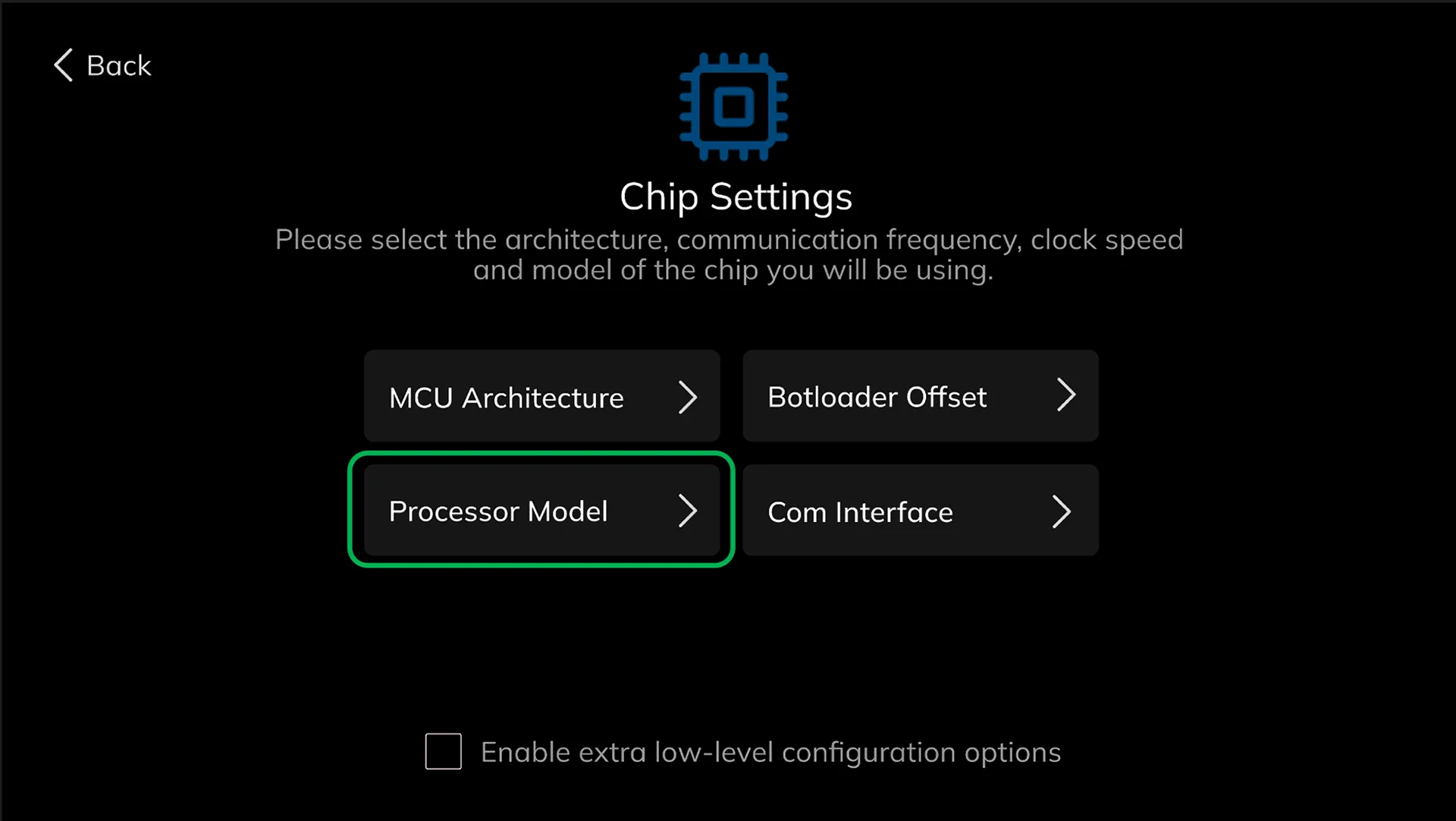
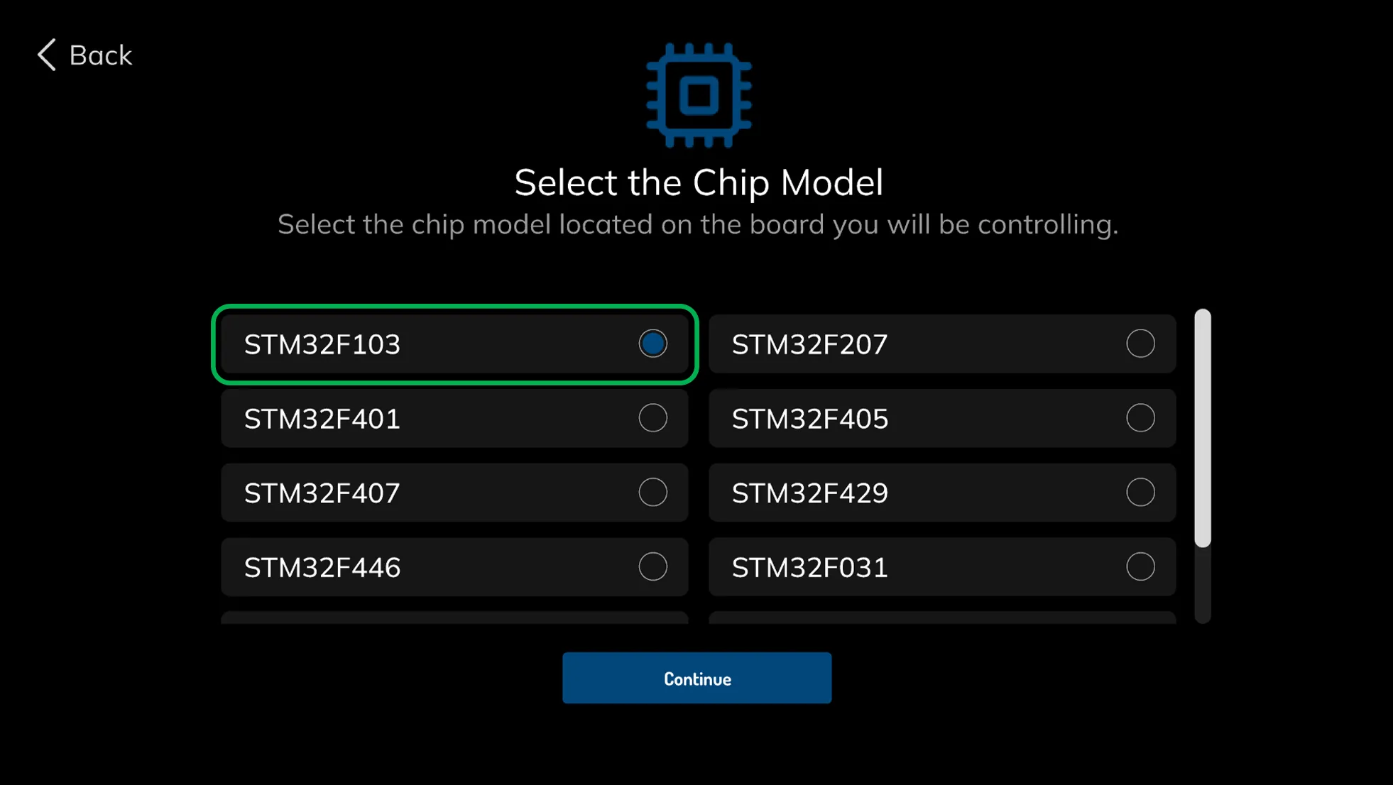
On the Processor Model page, select the STM32F103, which is the processor model found on the control board of the Ender 3 V2. Then, click on the continue button.
¶ 1.7.4 Select the Bootloader Value
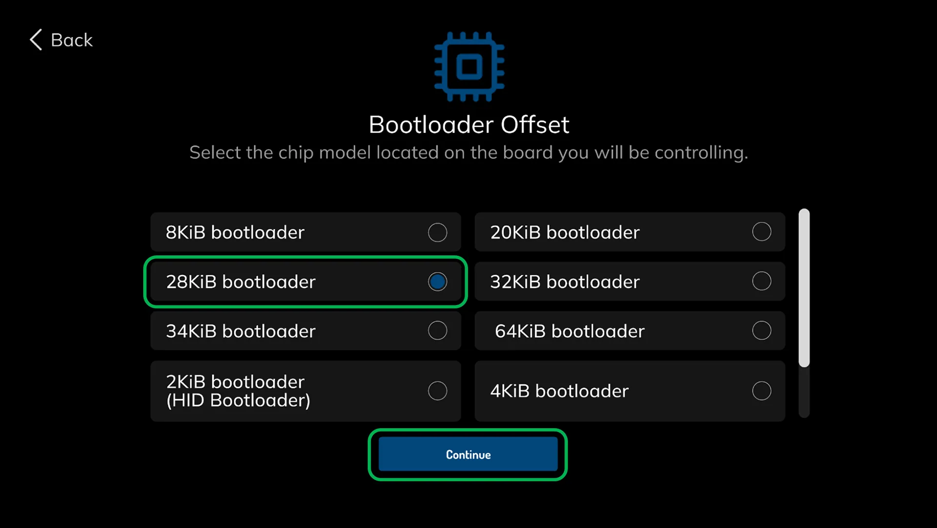
Now, we need to select the appropriate bootloader value for our printer. Go to the relevant tab to select the bootloader value. For the Ender 3 V2 model, choose the 28Kbit bootloader value and proceed.
Select the 28Kbit bootloader value, which is applicable for the Ender 3 V2 model, and proceed.
¶ 1.7.5 Select the COM Port
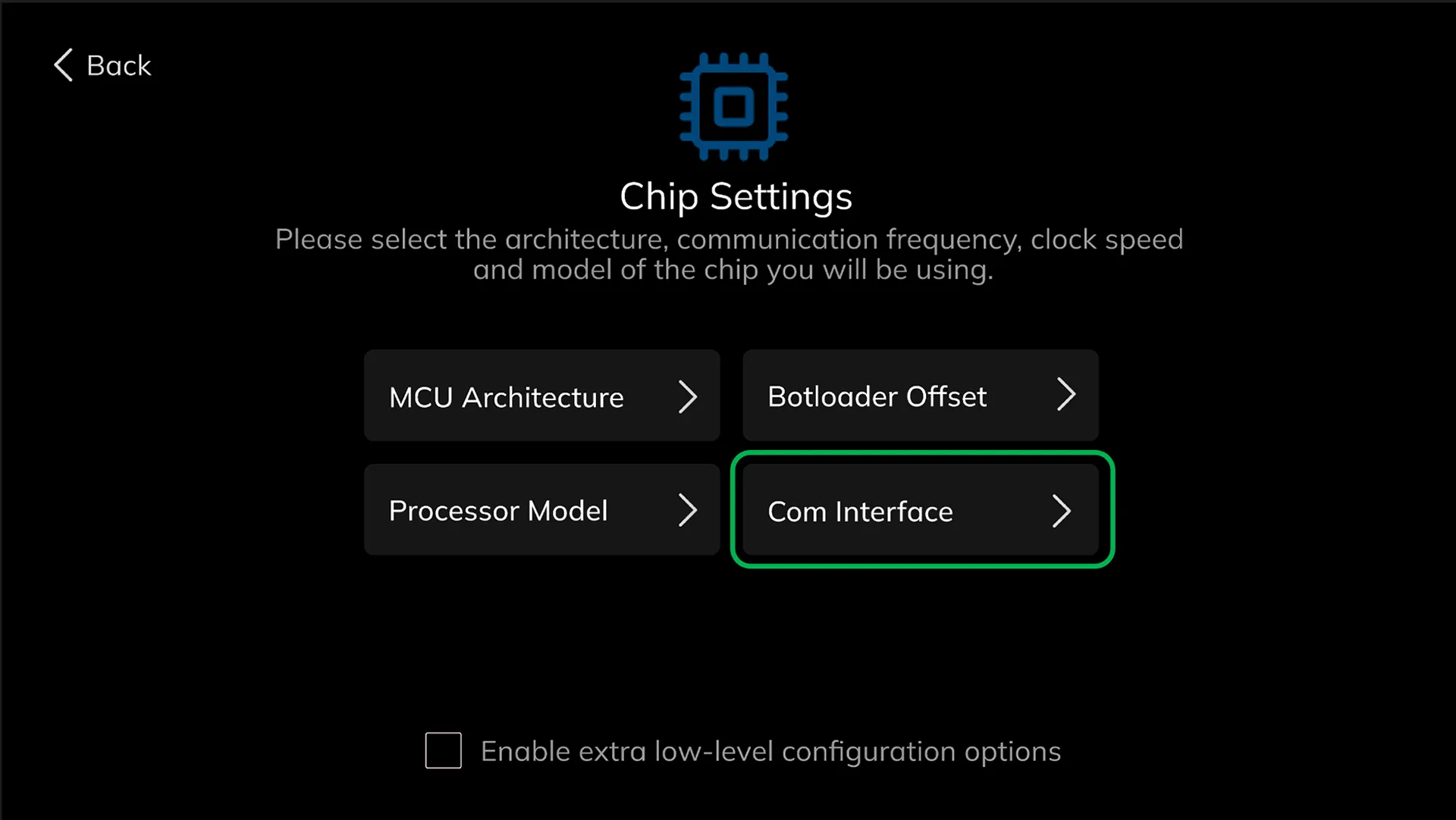
Finally, select the COM Port for ChromaPad to communicate with the printer
Select the "Serial (on USART1 PA10/PA9)" option, which is suitable for the Ender 3 V2, from the Com Interface menu.
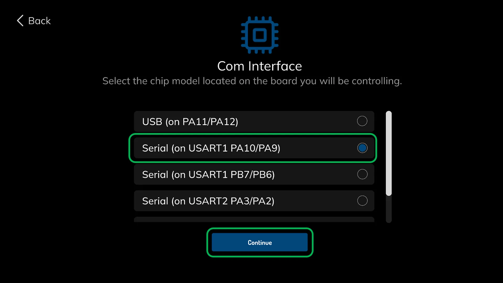
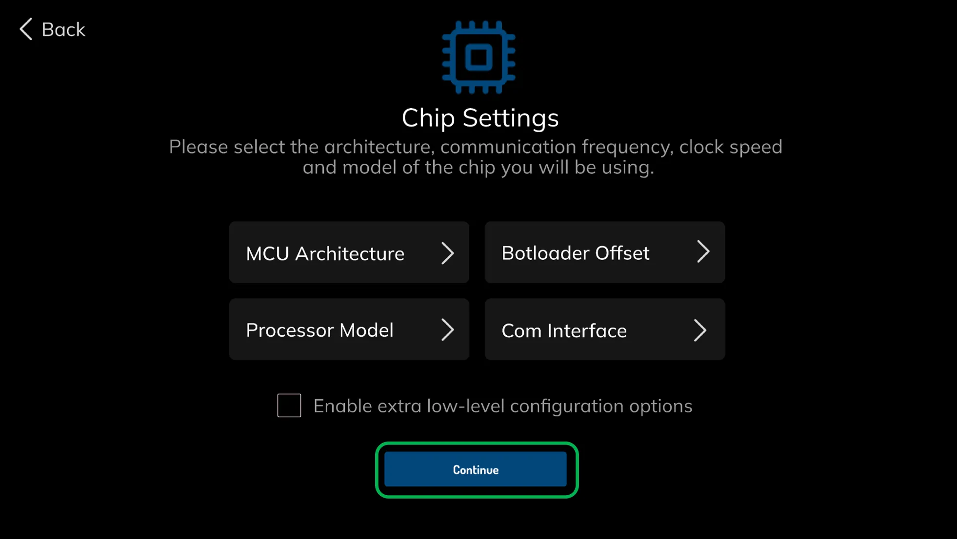
All necessary settings have been made, and our manual setup process is complete. Click on the continue button to proceed to the binary file creation screen.
¶ 1.7.6 Compile the Manually Generated Binary File
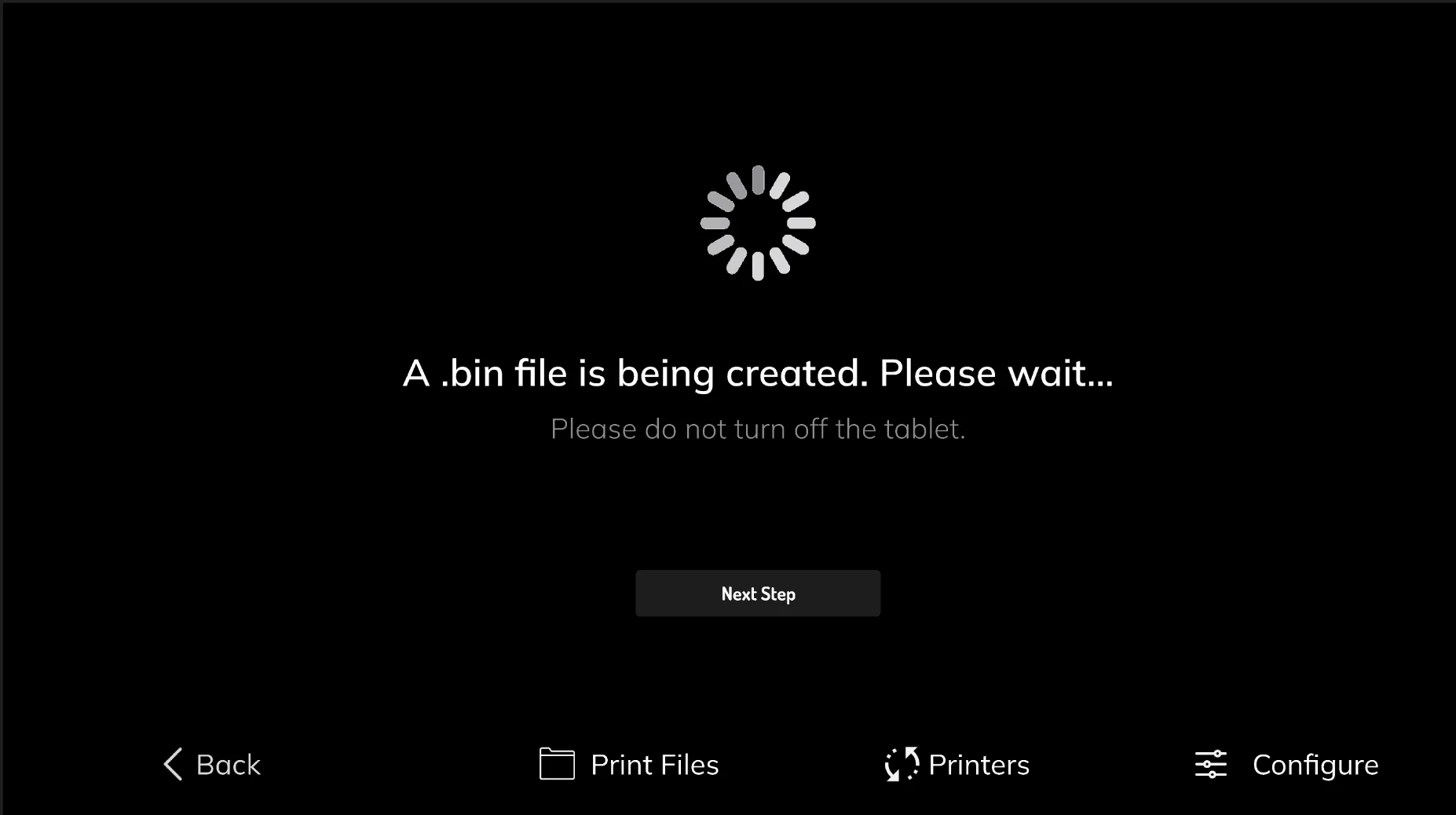
The manually generated binary file is currently being compiled. This process may take some time. Please refrain from performing any actions during this time.
¶ 1.8 Write the Generated Binary File to the SD Card
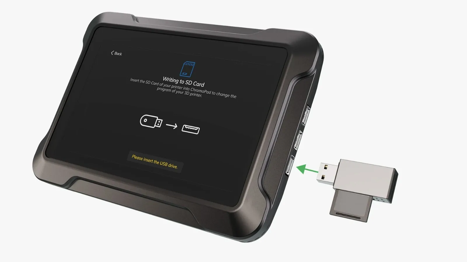
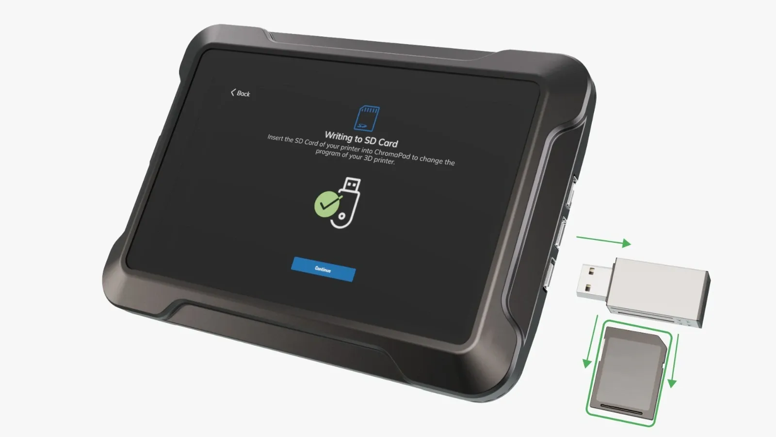
When the process is complete, the screen for inserting the SD card reader into the USB ports will appear automatically. When this screen appears, please insert the SD card reader, along with the SD card where the binary file will be written, into the tablet.
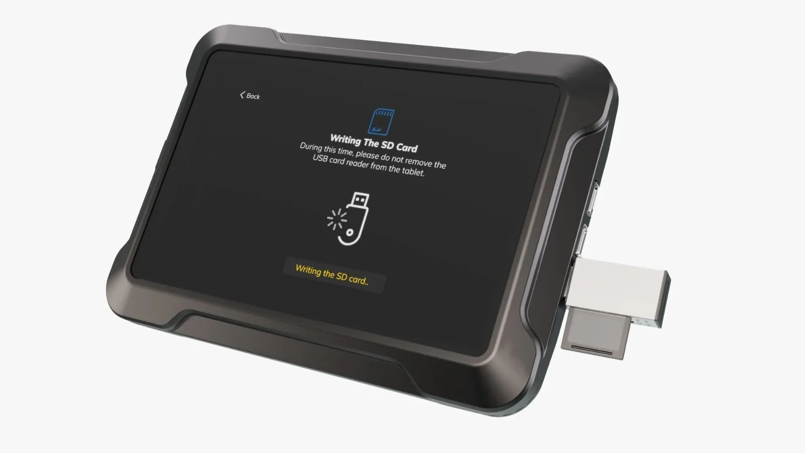
When the card reader is inserted, the writing process to the SD card will start automatically. Please refrain from performing any actions until the confirmation screen appears.
When the writing process to the SD card is successfully completed, you can remove the SD card reader from ChromaPad when the screen indicates so.
¶ 1.9 Write the binary file to your printer
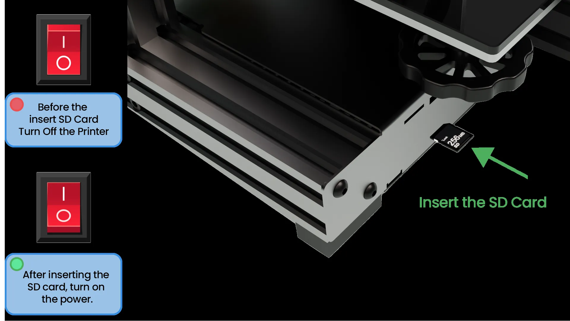
Insert the SD card, which you removed from the SD card reader, into your 3D printer while the printer is powered off. Then, turn on the power of the 3D printer and wait for the printer to boot up. If the screen of your 3D printer doesn't display anything, the process has been completed.
¶ 1.10 3 Connect your 3D printer to ChromaPad
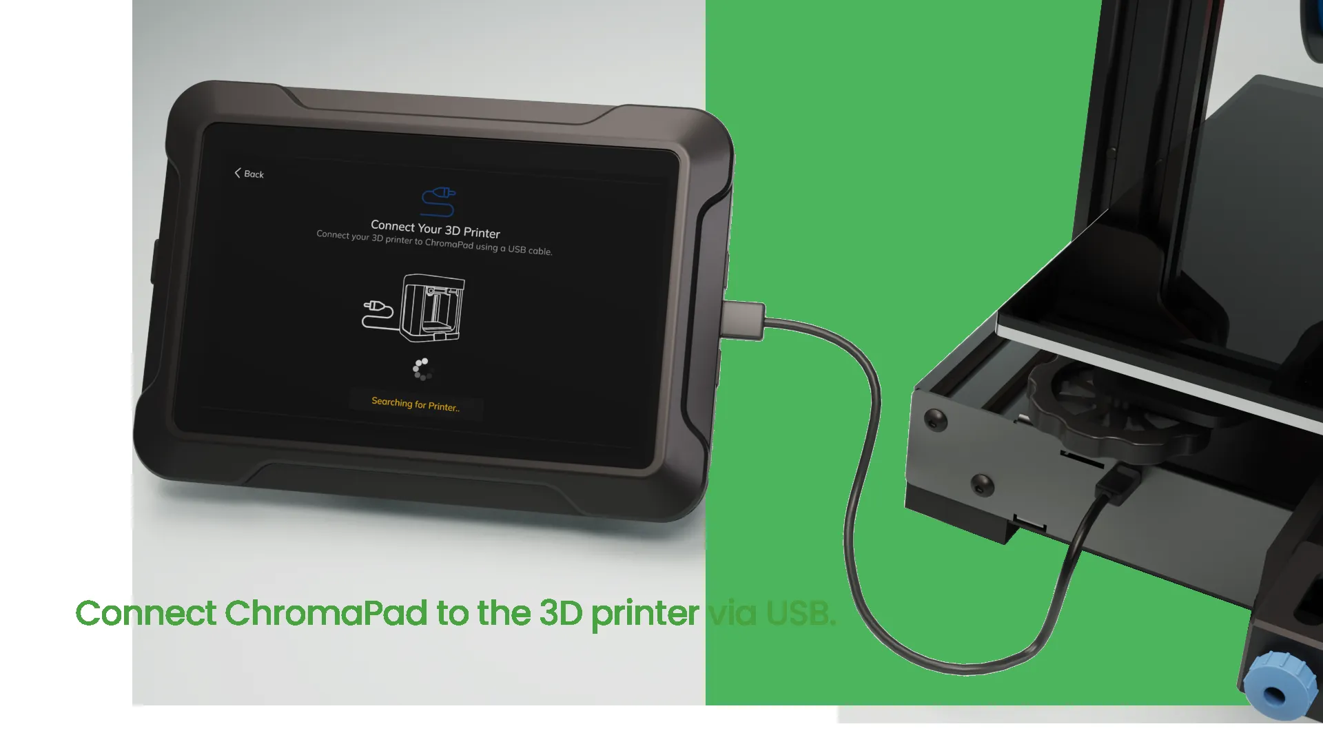
We've successfully uploaded and programmed the binary file to your printer. Now, connect your printer to ChromaPad using the USB cable provided in the box.
¶ 1.11 Select the Connection Port
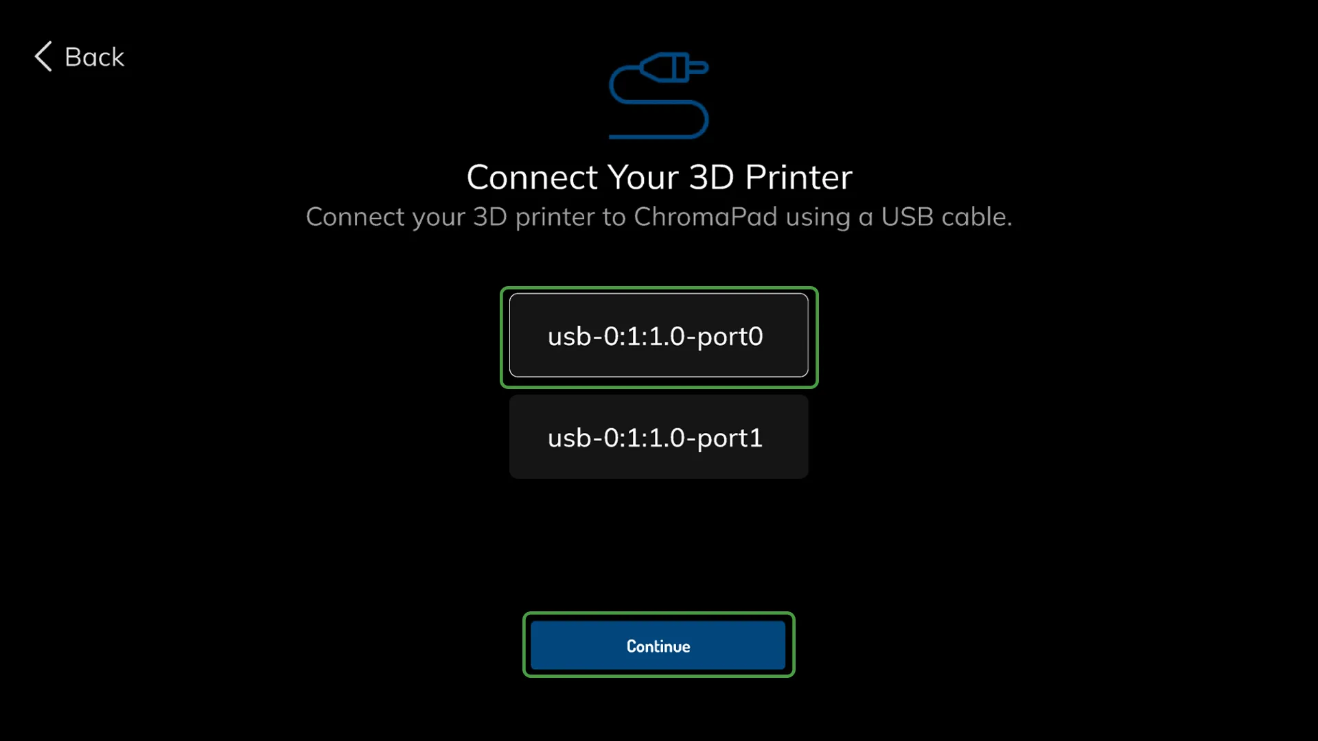
Choose which USB port on ChromaPad you have connected the printer to, and select the USB path accordingly.
¶ 2.0 Connect ChromaHead to the 3D Printer
¶ 2.1 Remove old Toolhead & carriage
To attach ChromaHead to your printer, you need to remove the stock toolhead that came with your printer. You can learn how to remove the stock toolhead in the case of the Ender 3 V2 by watching a video. For other printers, you can click here to get detailed information.
¶ 2.2 Attach the ChromaHead carriage to the Sigma Profile and Non-Sigma Profile
¶ Sigma Profile
You need to install the specially designed carriage for ChromaHead that came with the ChromaSet in place of the removed stock carriage. Since this carriage uses stock screws, nuts, and wheels, installation is straightforward. Use an allen key and a wrench to perform the installation.
¶ Non-Sigma Profile
The situation is exactly the same for non-Sigma printers. You can use the part specially designed for your printer by printing it from your printer. Click to go to printable parts.
¶ 2.3 Install the belt onto the carriage
After attaching the screws and wheels, we pass the belt through the points on the carriage.
¶ 2.4 Remove the Front Cover of ChromaHead
To attach ChromaHead to the carriage, the necessary screws are located inside the cover. Therefore, we start the assembly process by removing the front cover.
¶ 2.5 Align ChromaHead with the carriage
After removing the cover of ChromaHead, align it with the carriage attached to the Sigma Profile and insert the screws into the aligned screw holes.
¶ 2.7 Secure ChromaHead to the carriage
After aligning the carriage with ChromaHead, use the M3x10 screws provided in the set to secure ChromaHead to the carriage at the indicated locations.
¶ 2.8 Installation of ChromaHead Cable
In this step, we're attaching the ChromaHead connection cable that comes with the ChromaSet and securing it with the M3x10 screws provided in the set.
Insert the other end of the ChromaHead cable into the ChromaHead slot located on ChromaPad.
¶ 2.9 Installation of 8in1
To connect the filament, rotate the 8in1 module and insert it into the threaded socket.
¶ 3. Mounting the CX-I Extruder
Place the screws and T-nuts onto the CX-I Holder piece, designed to mount the CX-I Extruders onto the Sigma Profile.
¶ 3.1 Place the CX-I Holder onto the Sigma Profile
Hold the T-nuts parallel to the channels of the Sigma Profile and insert them into the profile. Then, place the Holder.
¶ 3.2 Tighten the connection screws
The screws on the Holder are tightened using an Allen key. The Holder is then secured onto the Holder Sigma profile.
¶ 3.3 Place the CX-I Extruder
The CX-I Extruder is placed on the upper surface of the holder. From the bottom surface, the Extruder motor is also positioned. The shaft of the Extruder motor and the gear on the shaft fit into the CX-I. Following this step, screws are tightened using an Allen key to assemble all parts of the extruder.
¶ 3.4 Correct Positioning of CX-I Extruders
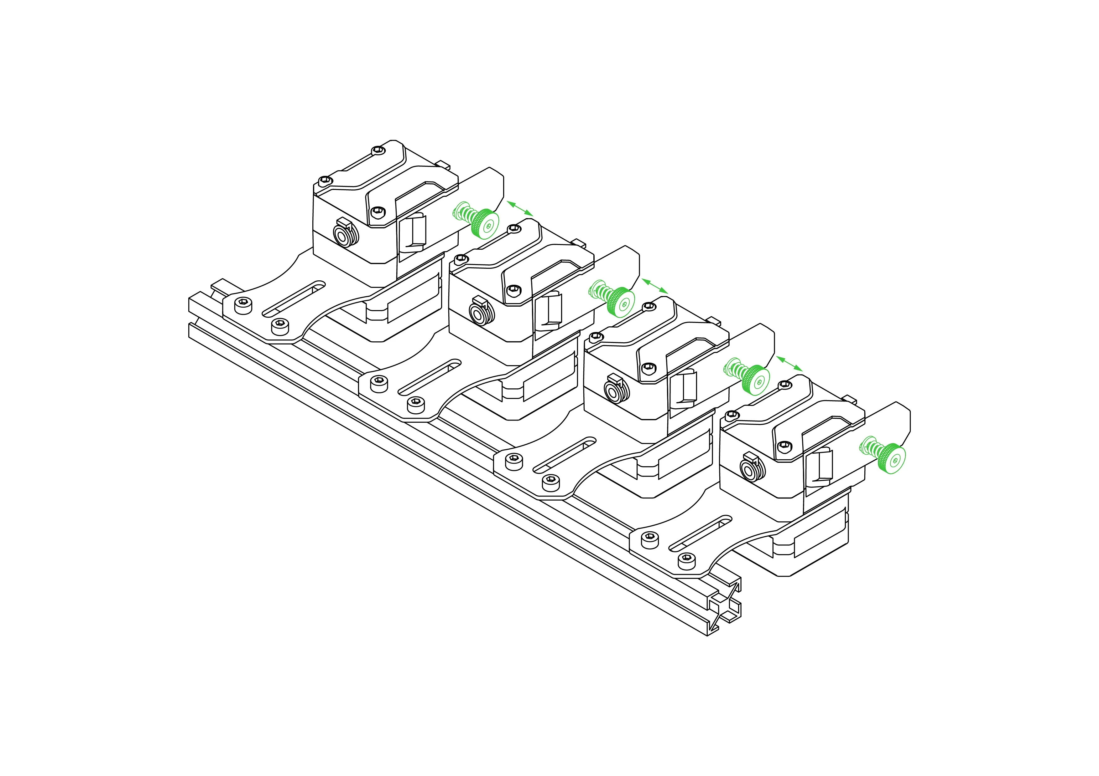
You can place the 4 extruders that come out of the ChromaSet onto the sigma profile like this, or if you prefer, you can use additional parts to use them on the table. During placement, adjust the distance between the extruder clamps to ensure comfortable use.
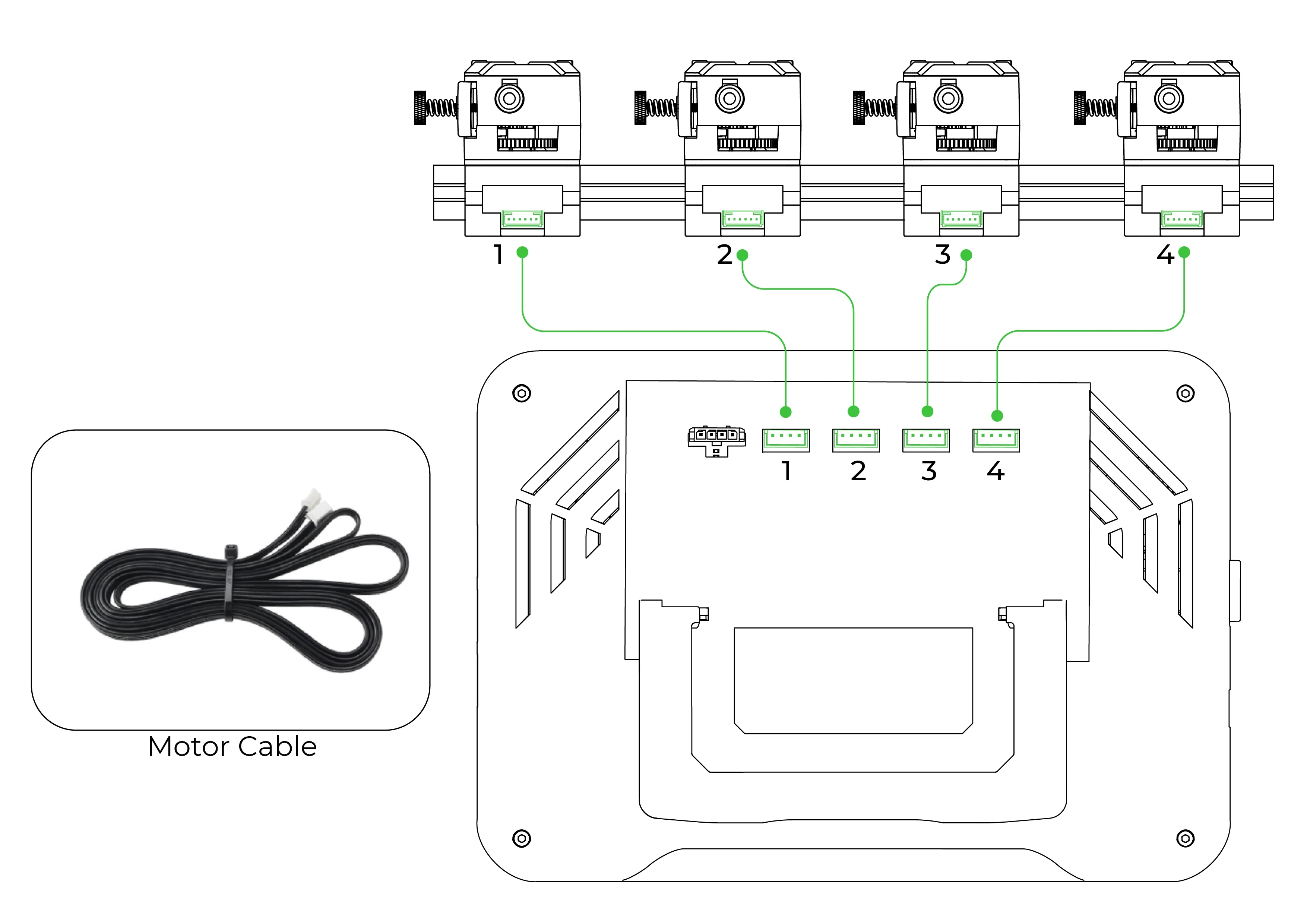
¶ 3.5 Connecting the Extruder Cables to the ChromaPad
The cables of the extruders are located within the ChromaSet. Please connect the cables to the extruder sockets on the ChromaPad as shown in the diagram.
