¶ 1-Before starting the installation, please make sure to print the required STL files using your 3D printer in its original stock configuration.
| Part Name | Quantity | Links |
|---|---|---|
| ChromaHead Mounting Bracket | 1x | Download |
| CX-I Holder for Sigma | 4x | Download |
| PTFE Tube Holder | 2x | Download |

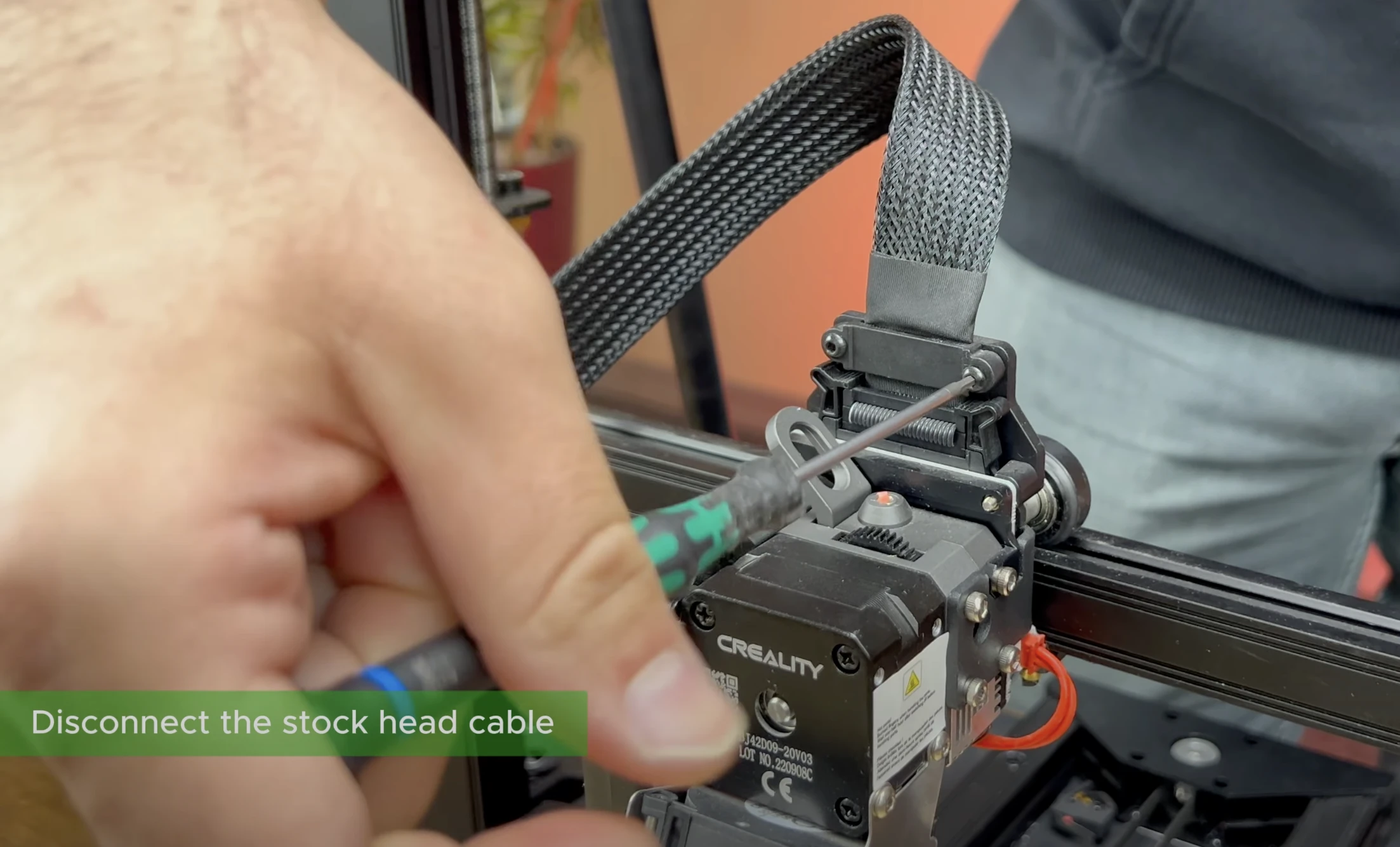
¶ 2- Disconnect the Cable of the Stock Printhead
Remove the cable from the stock printhead, which is secured with two hex socket screws.
¶ 3- Remove the Screws Holding the Extruder
Using an Allen key, remove the screws located on the right side of the printhead that are used to secure the extruder.
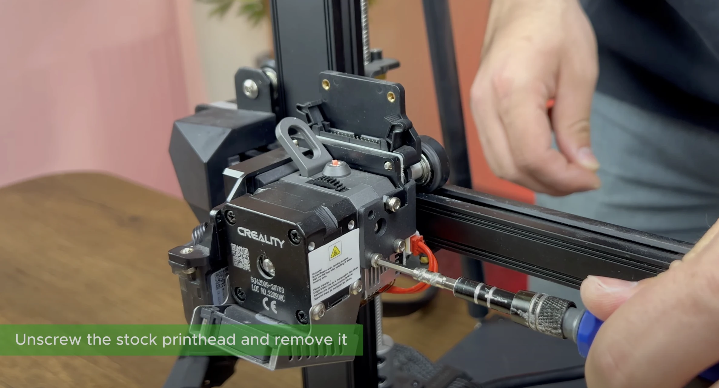
¶ 4- Remove the Stock Printhead
After removing the screws, pull the printhead forward to detach it from its position.

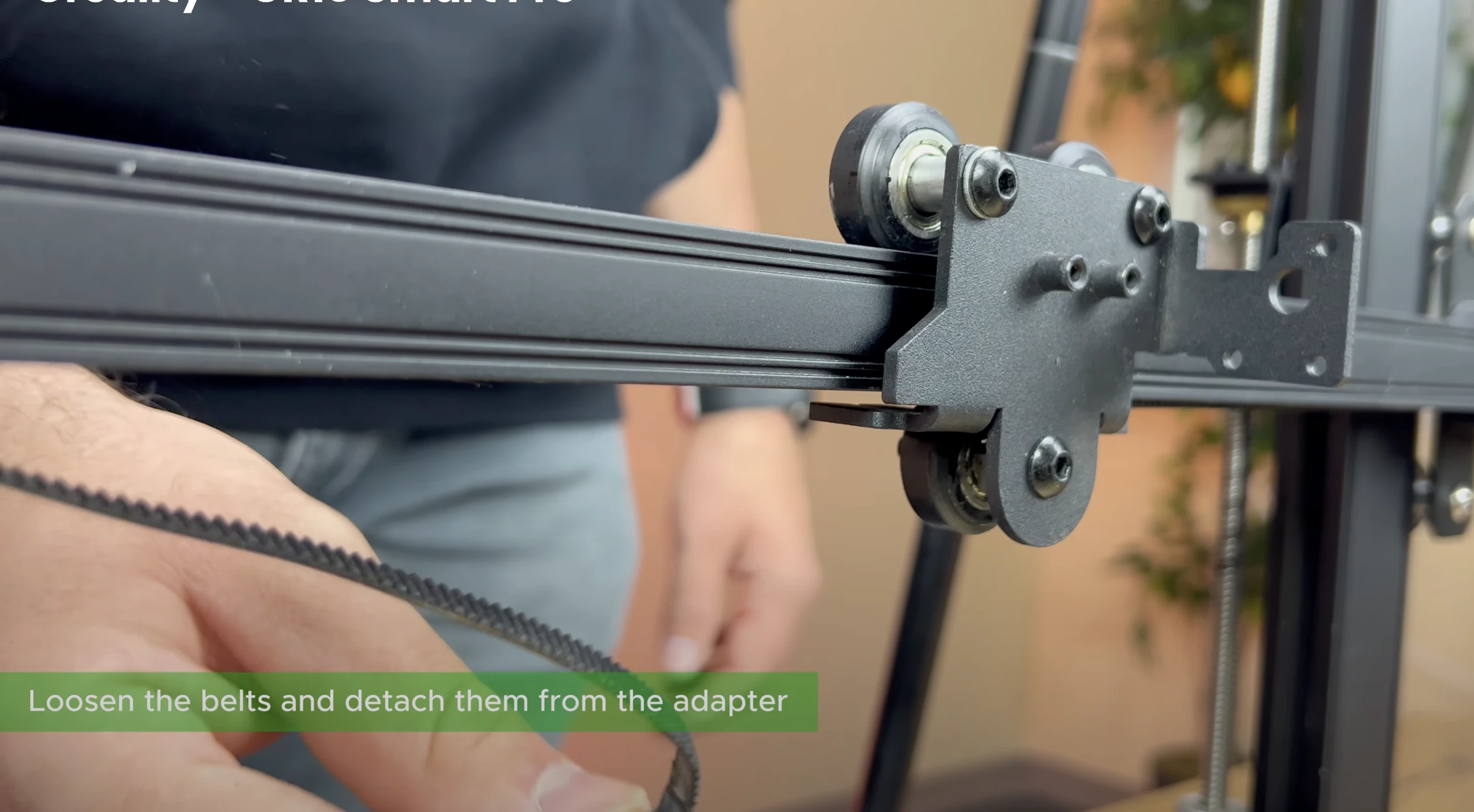
¶ 5- Loosen the Belt
Loosen the adjustment screw located on the right side of the printer to release the belts.

¶ 6- Detach the Belts from the Carriage
After loosening the belts on the right and left sides of the carriage, push them backward to detach them from their positions on the carriage.
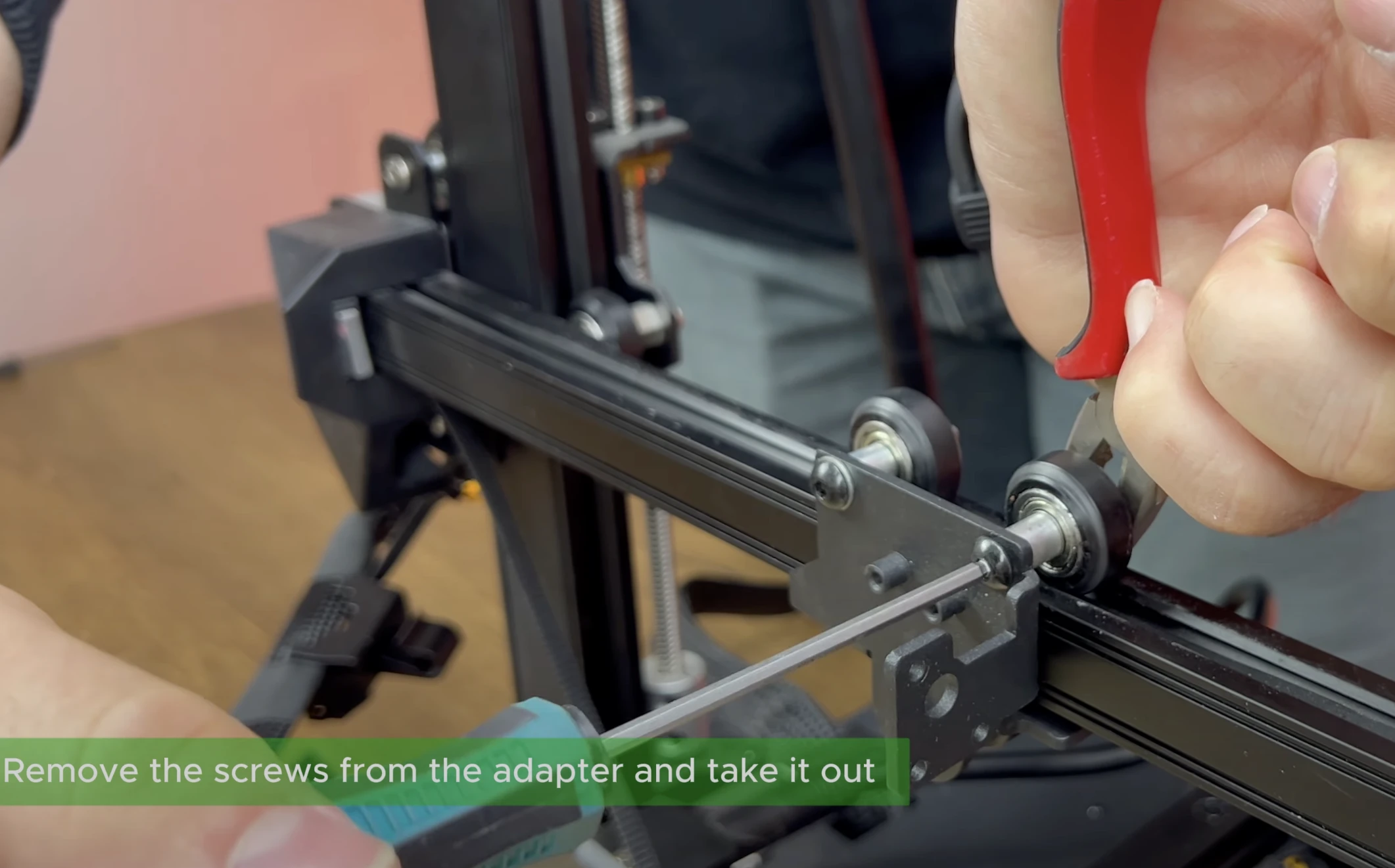
¶ 7- Deatach the Carriage from the Sigma Profile
Using wrench or pliers and an Allen key, remove the wheels on the carriage and then take the carriage off the rail.
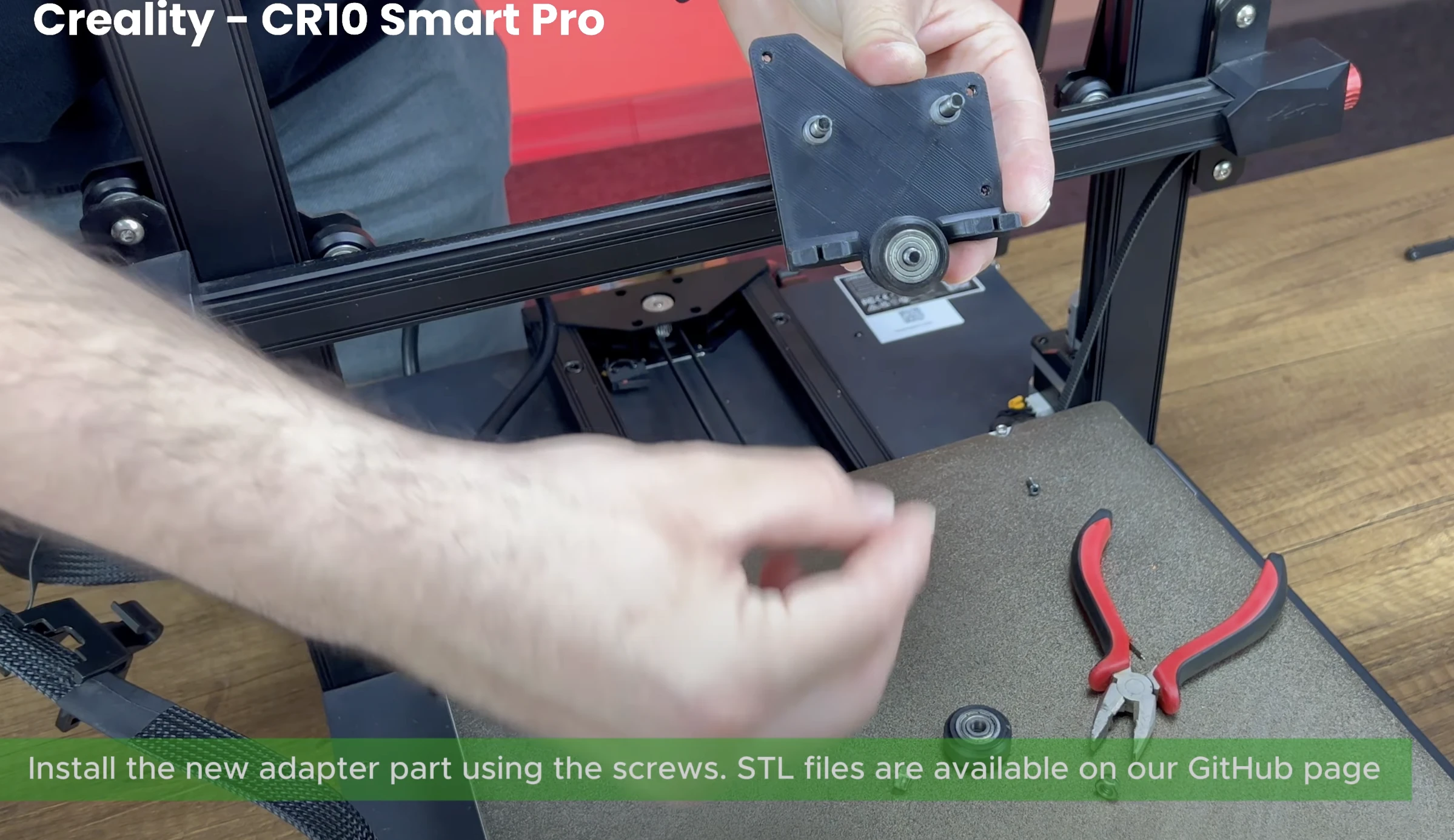
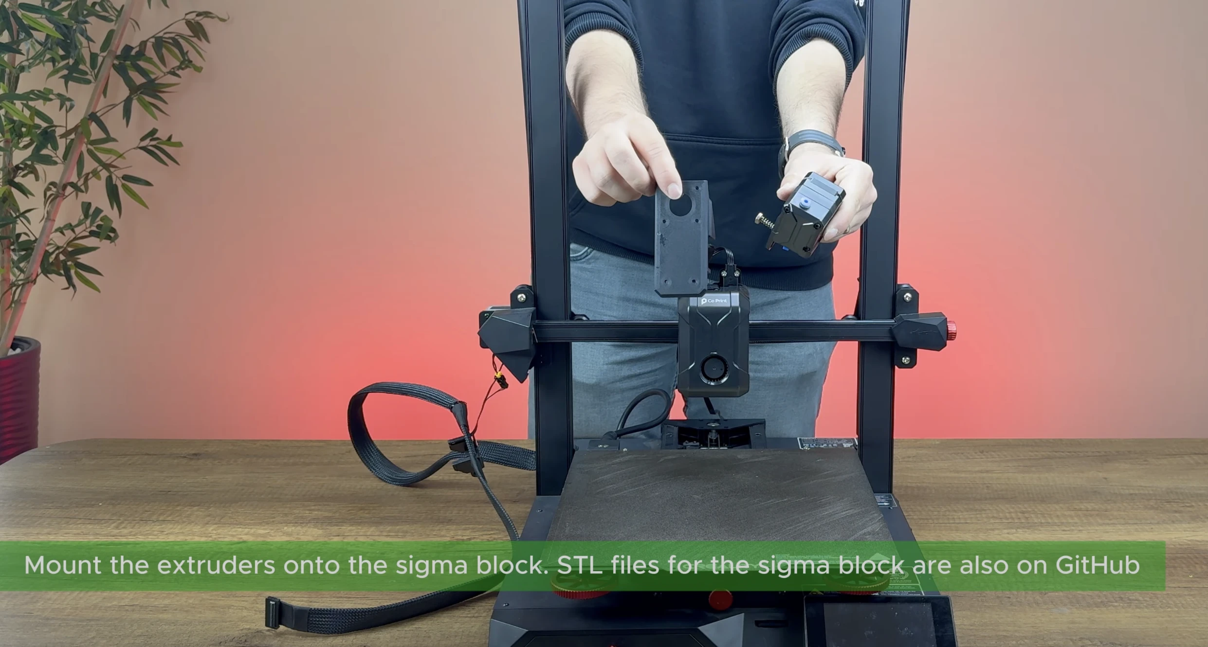
¶ 8- Install the ChromaHead Adapter
Take the ChromaHead adapter part you downloaded and printed before the instillation, and prepare it to be mounted onto the carriage.
.

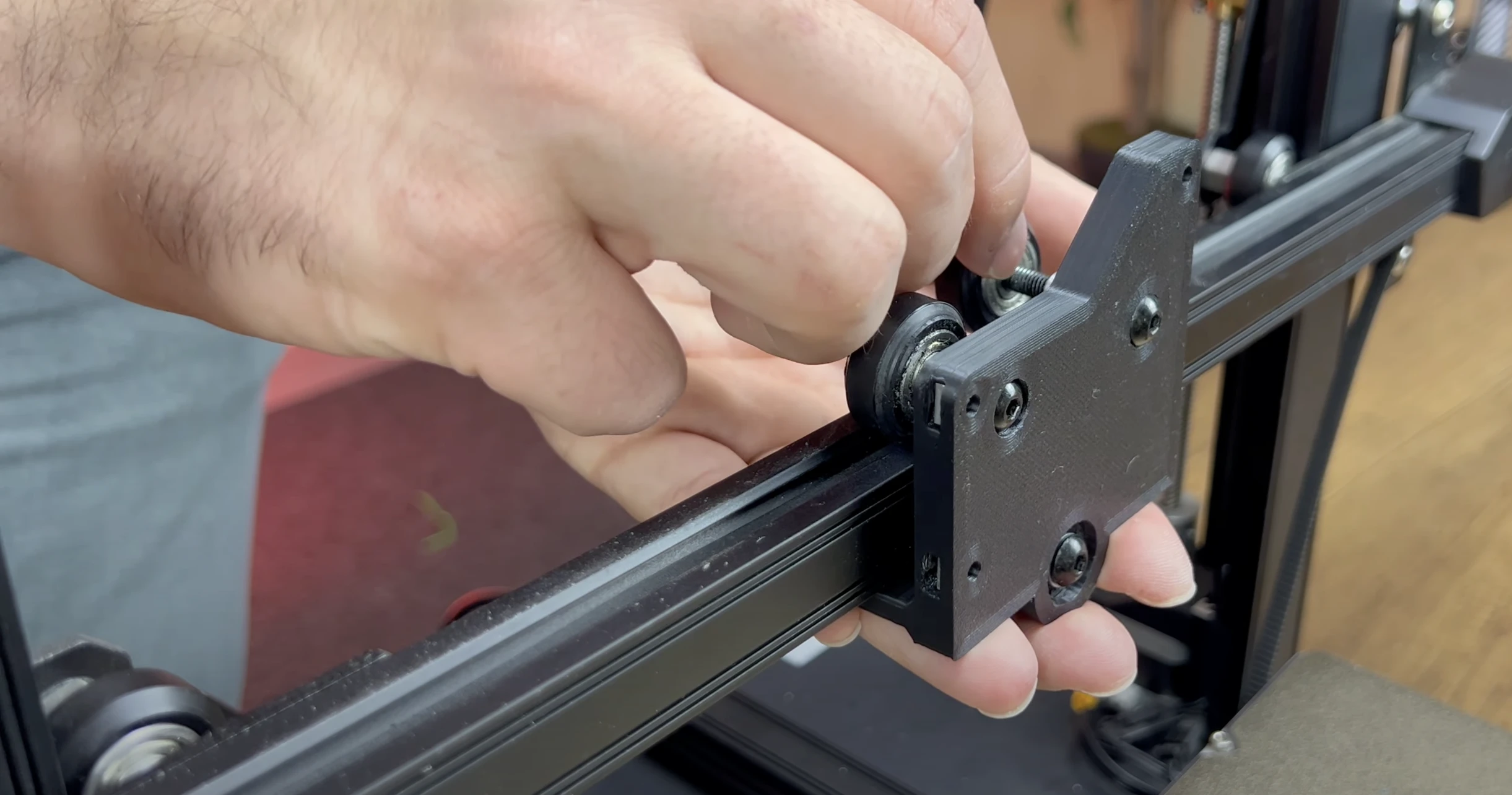
¶ 9- Attach the Wheels to the Printed Carriage
Using the bolts and nuts removed from the old carriage, attach the wheels to the ChromaHead adapter part.
¶ 10- Complete the Carriage Assembly
Complete the carriage assembly as shown in the picture. Make sure it is not loose.
¶ 11- Attach the Belts to the Printed Carriage.
Attach the belts to the new ChromaHead carriage and readjust the belt tension.

¶ 12- Insert the Square Nuts
Insert the square nuts that came in the box into the designated spots needed to mount the ChromaHead onto the carriage.

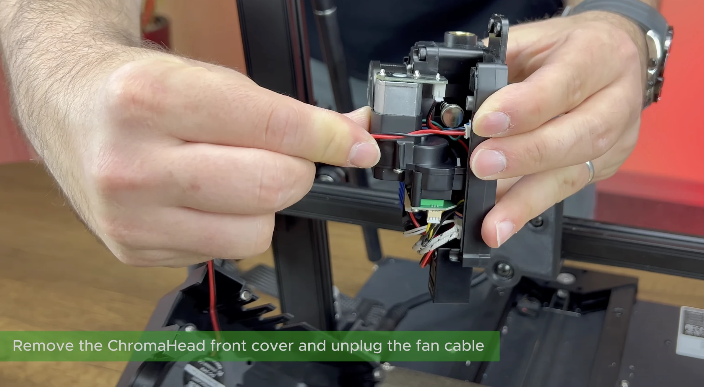
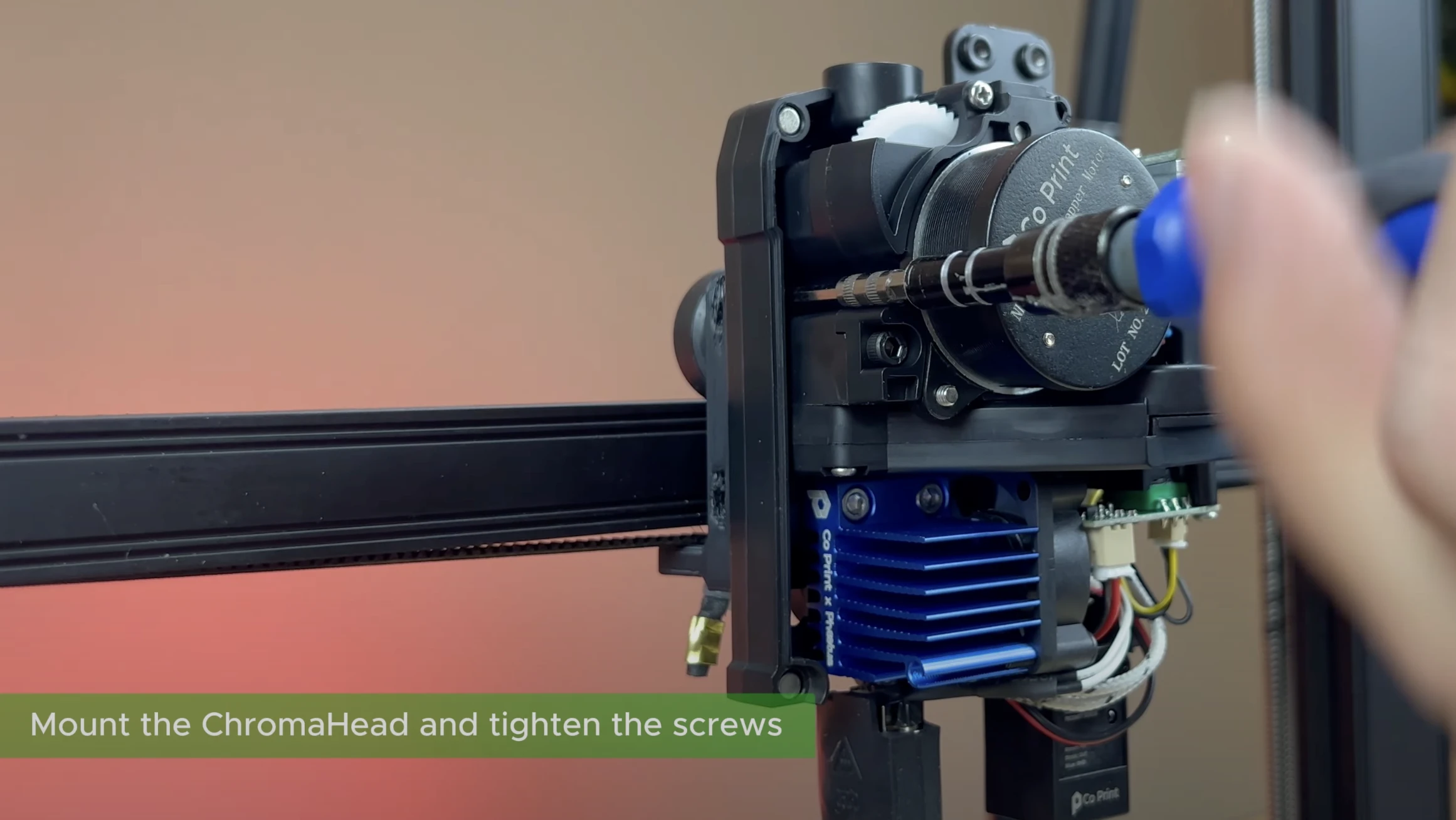
¶ 13- Secure the ChromaHead to the Printer
Open the ChromaHead cover, disconnect the fan cable, and remove the front cover. Then, secure it to the printer using the necessary screws through the mounting holes. There is one screw on the right side and two screws on the left side; tighten these screws using an Allen key.

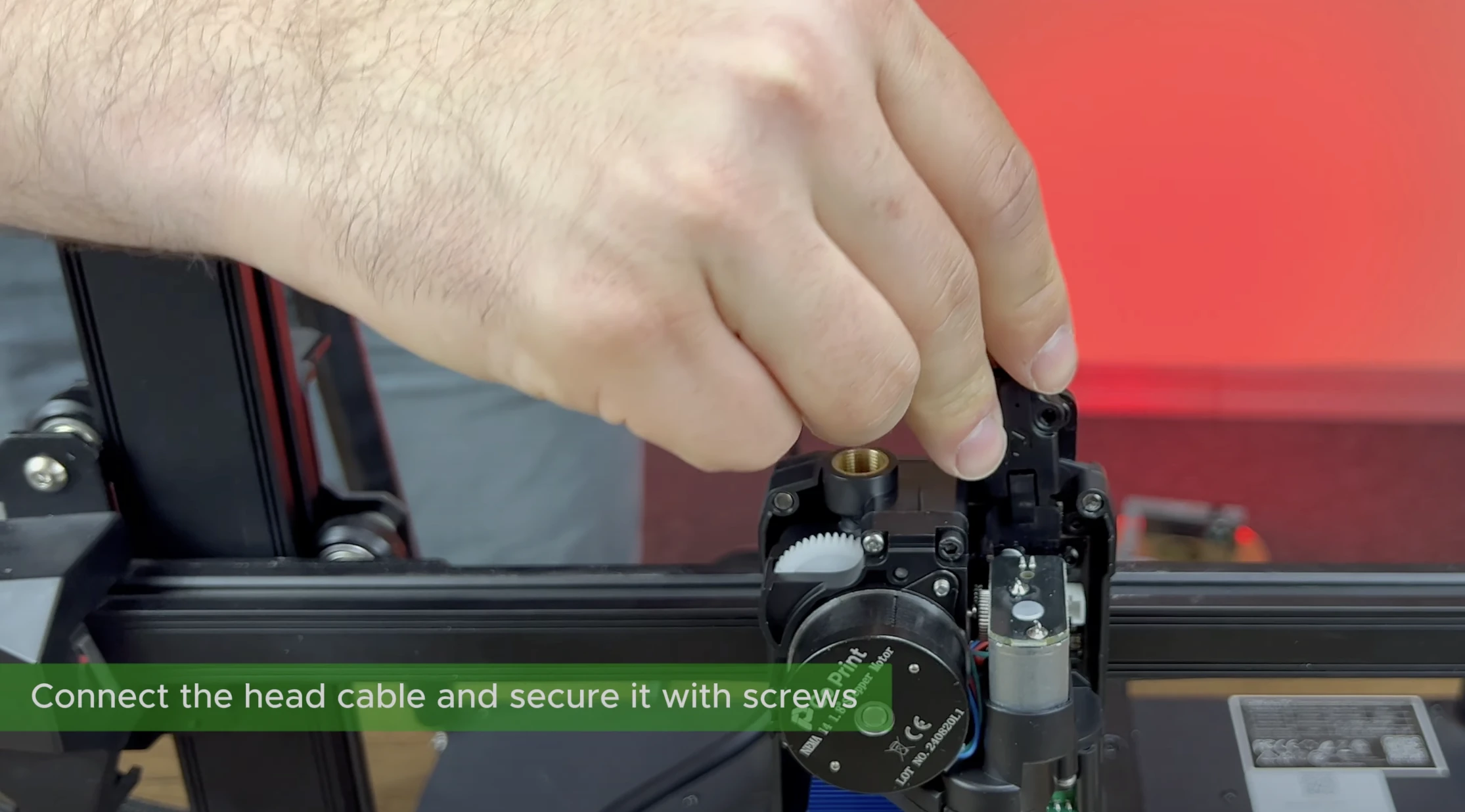
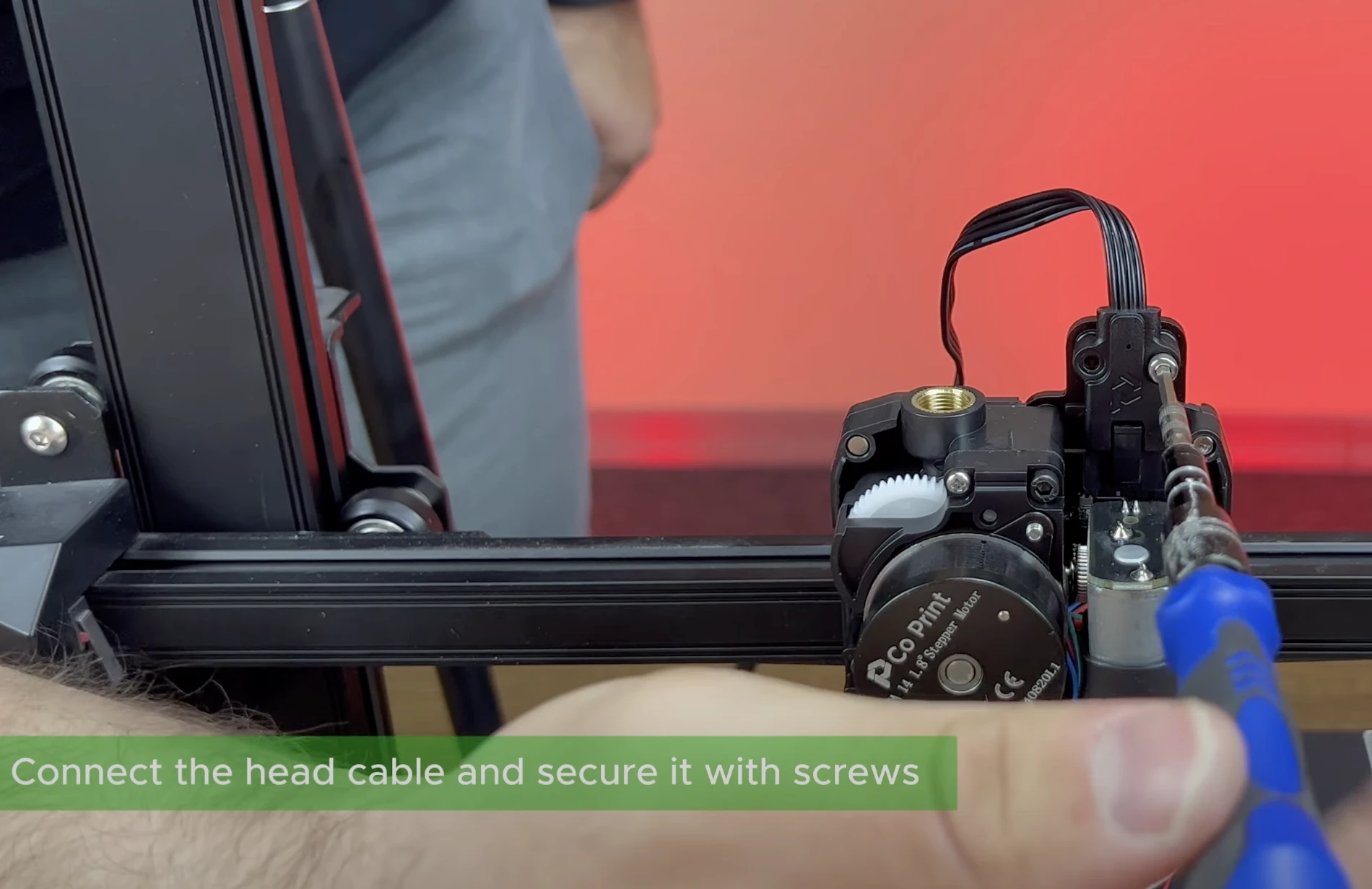
¶ 14- Connect the Chromahead Cable
Insert the ChromaHead cable into the socket.
Do not unplug or plug the ChromaHead cable while the KCM power cable is connected.
¶ 15- Attach the Screws for the Printhead Cable.
Secure the ChromaHead connection cable to protect it against vibrations. Use the screws provided in the box to fasten it firmly.
¶ 16- Attach the 8in1 Module
Rotate the 8in1 module from the box and place it in the designated spot. Make sure it is securely attached, but do not apply excessive force.

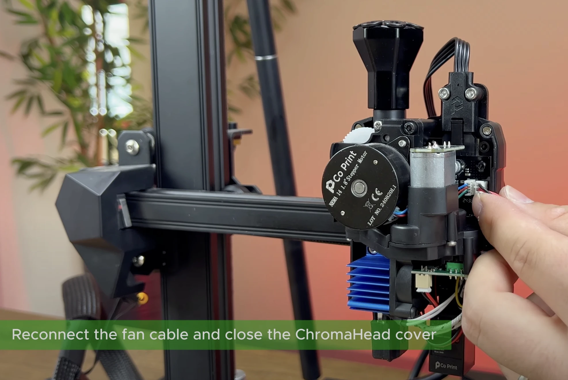
¶ 17- Close the ChromaHead cover.
After reconnecting the fan connector to the indicated spot, close the magnetic ChromaHead cover.
¶ 18- Attach the CX-I Holders
Take the 4 CX-1 holder parts which printed before the instillation and insert them between the split CX-1 units.
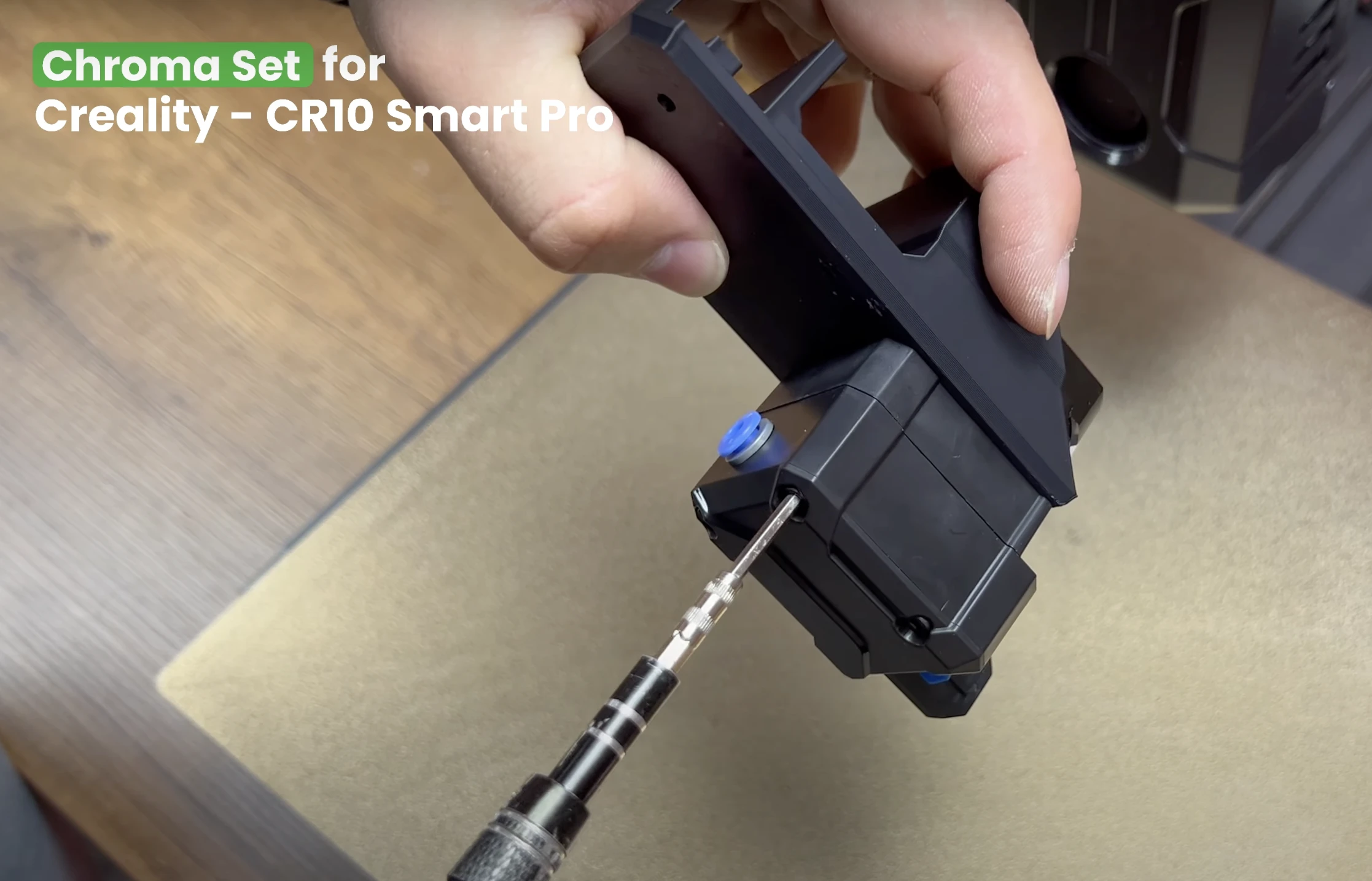
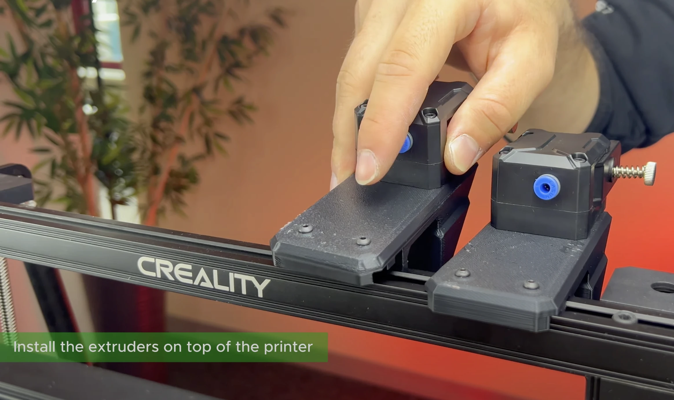
¶ 19- Attach the CX-I Holders to the Sigma Profile
Using the bolts and T-nuts provided in the box, secure the CX-I holders to the sigma profiles.
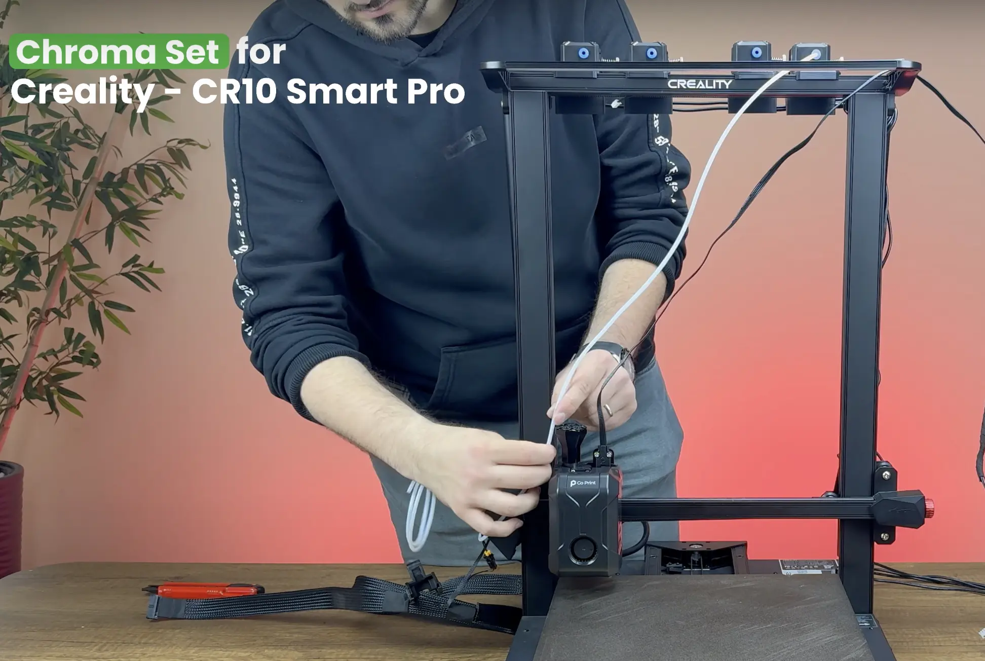
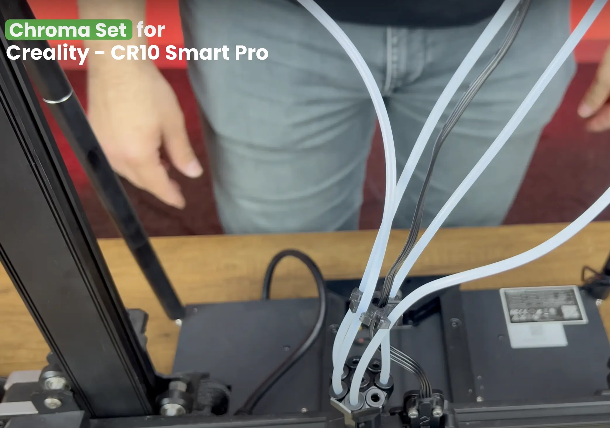
¶ 20- Install the PTFE Tubes
Adjust the printer’s head so that the motors are at the farthest position, then cut the PTFE tubes to the appropriate length and fit them into place. Repeat this process for each motor. Finally, to prevent tangling, secure the tubes together so they also cover the cables.
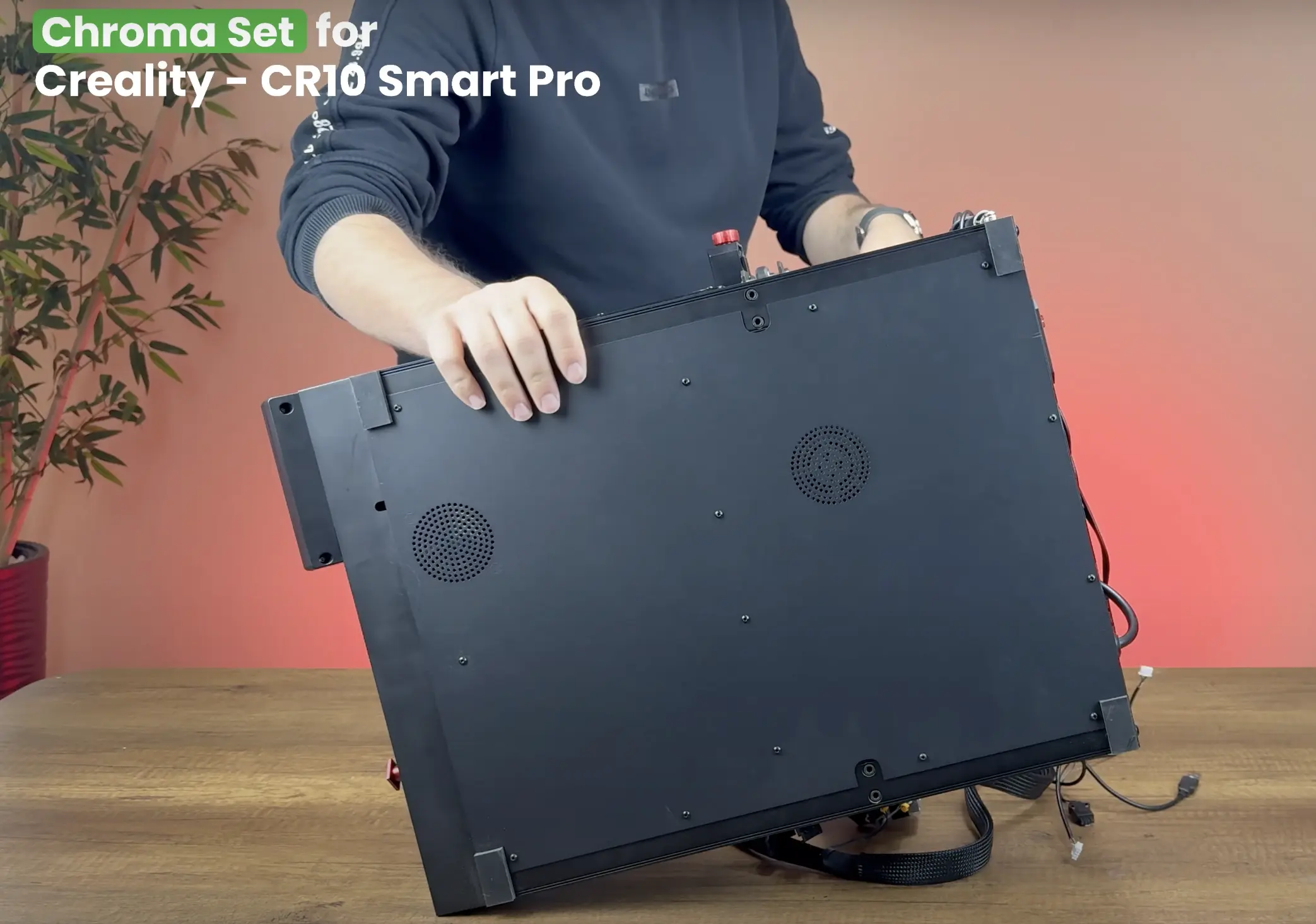
¶ 21- Remove Bottom Cover
To disable the start/stop button, unscrew the 15 screws located underneath the printer and remove the bottom cover. While removing the plate, detach the fan cable from its connector.
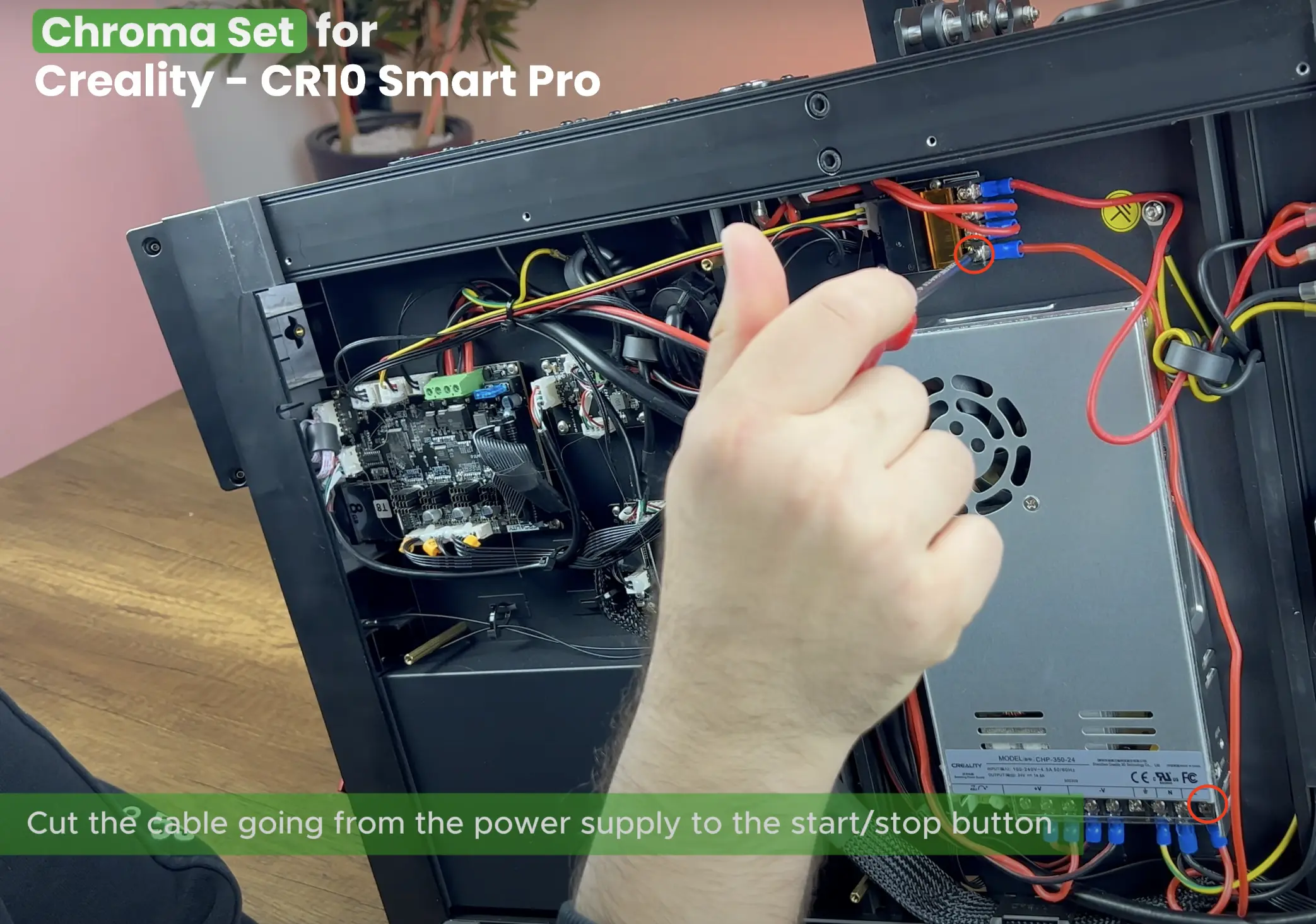
¶ 22- Disable the Start/Stop Button
Cut the cable going from the power supply to the start/stop button.

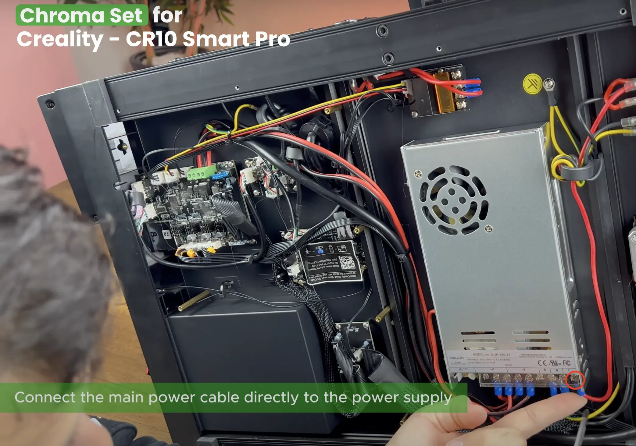
¶ 23- Connect the Main Power Cable
Connect the main power cable directly to the power supply.

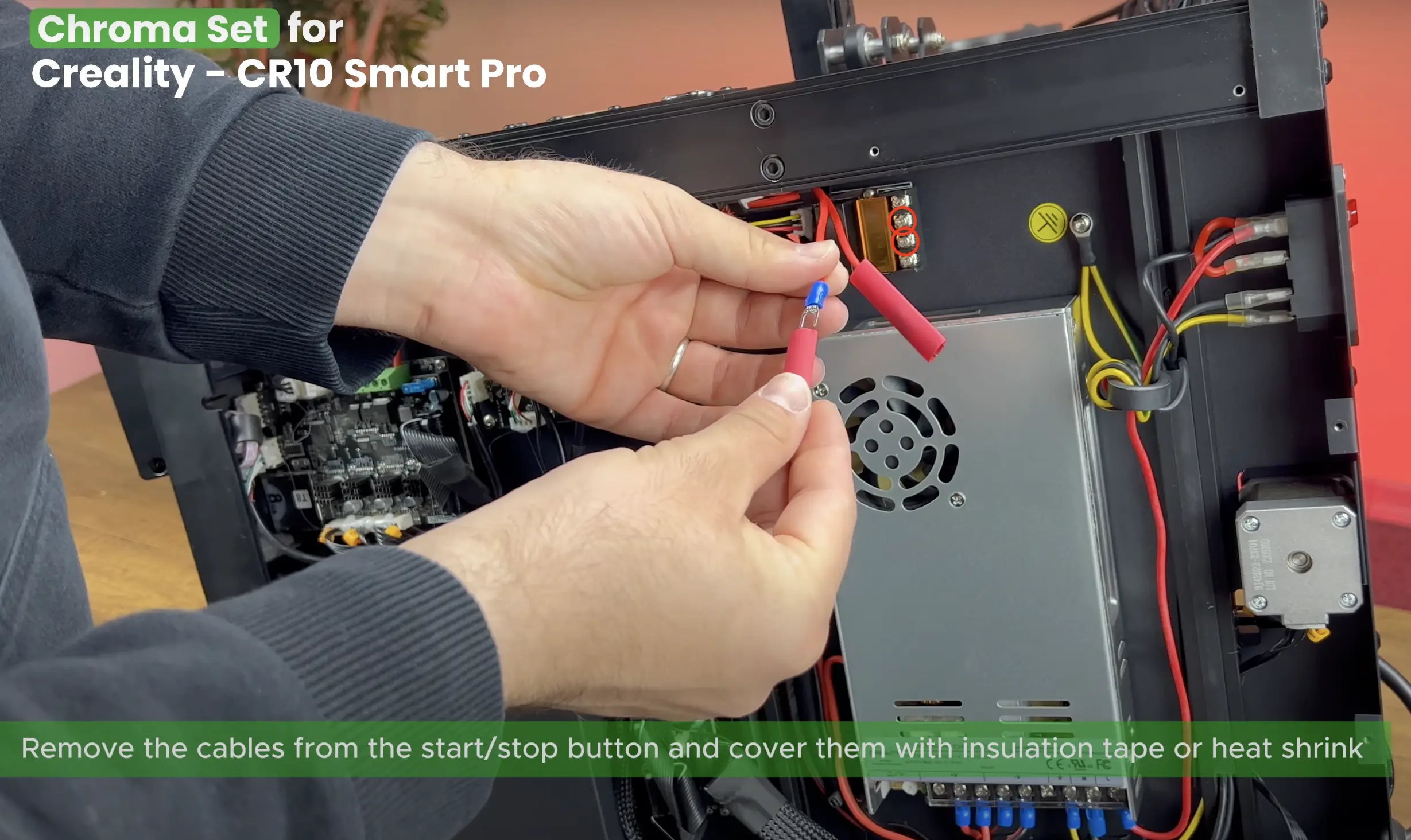
¶ 24- Remove the Cables from The Start/Stop Button
Remove the cables from the start/stop button and cover them with insulation tape or heat.
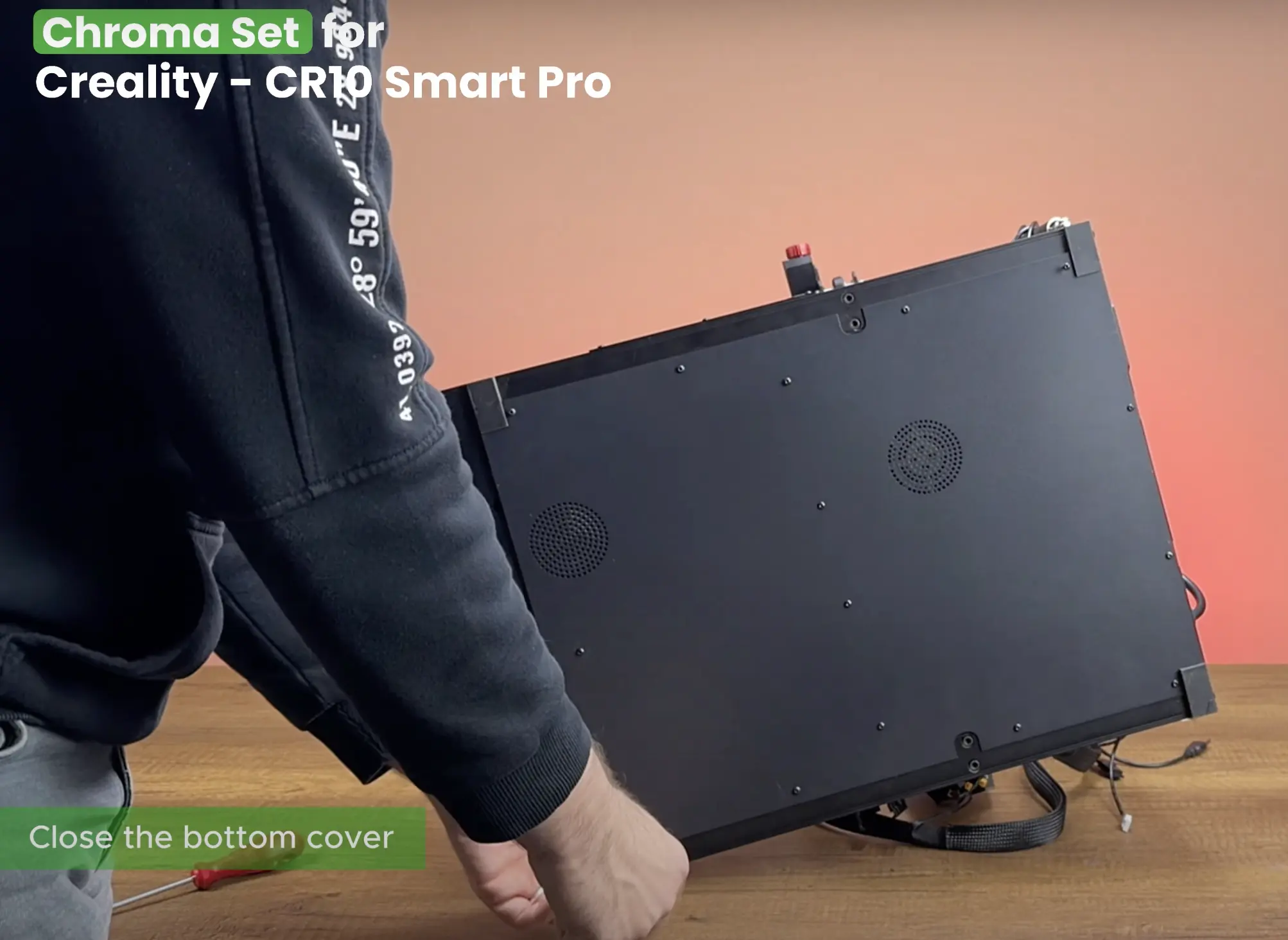
¶ 25- Close the Bottom Cover
Connect the fan cable back to its socket, then place the printer’s bottom cover back into position and reinstall the screws you removed earlier.
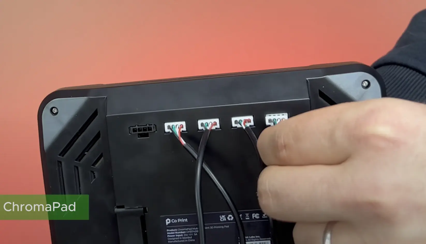
¶ 26- Connect the Motor Cables
Connect the motor cables to the ChromaPad in the correct order.
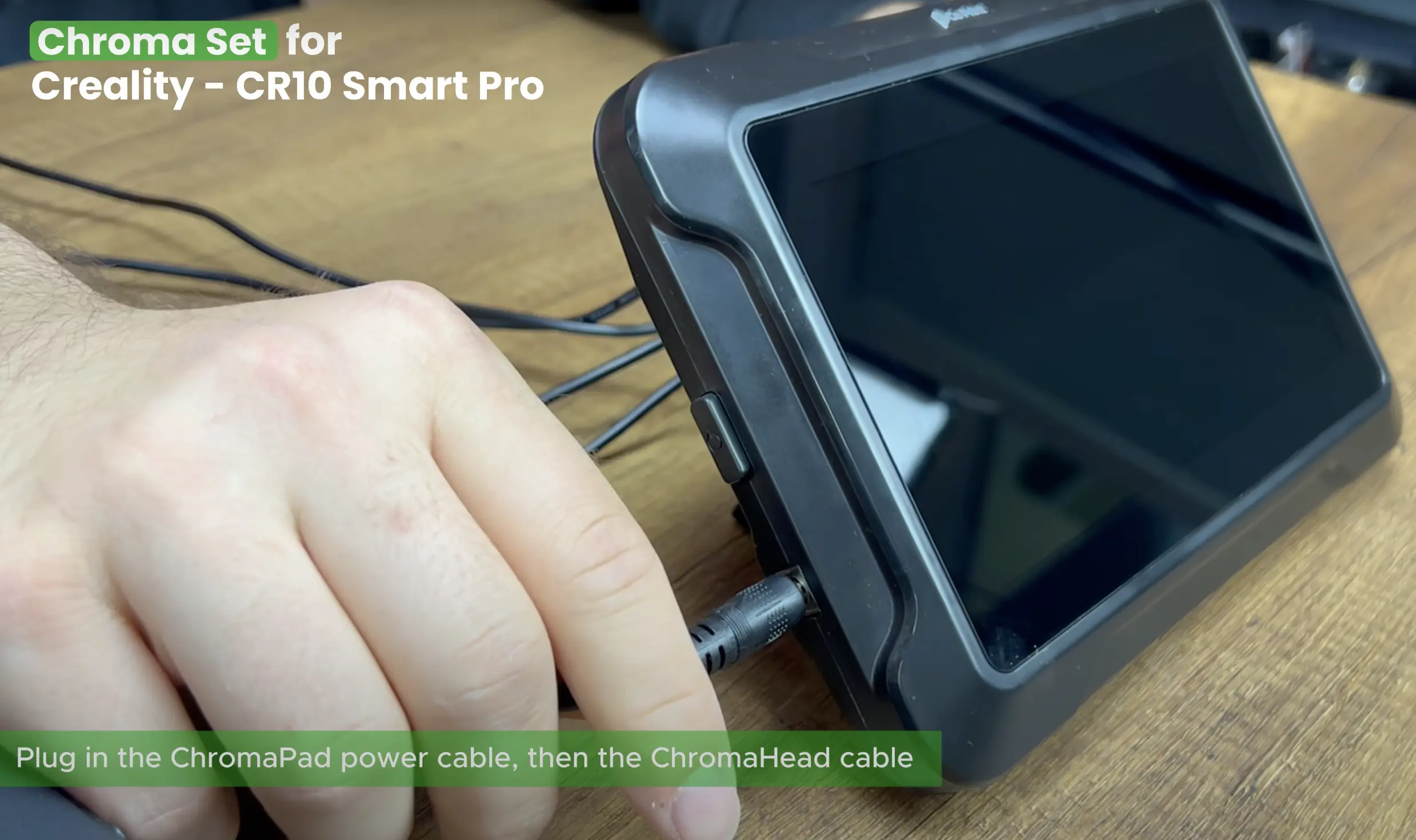
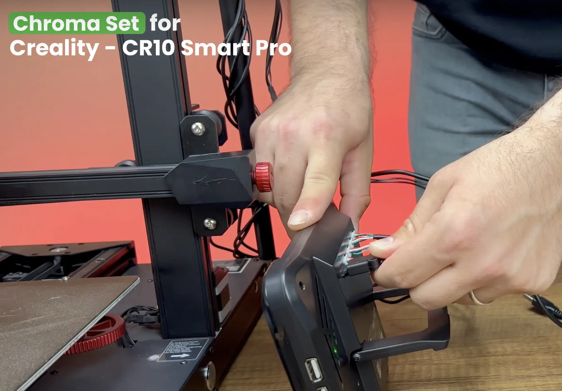
¶ 27- Plug in the ChromaPad Cables
Plug in the ChromaPad power cable, then the ChromaHead cable. Make sure the power is off before plugging in the ChromaHead cable.
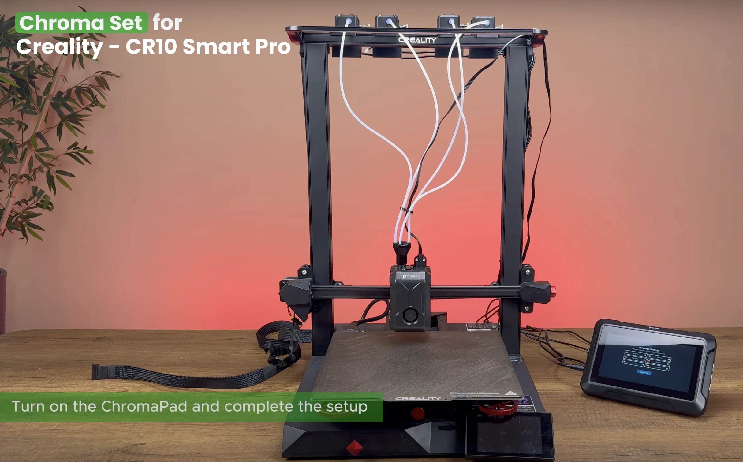
¶ 28- Turn the ChromaPad on
Turn on the ChromaPad and complete the setup. (Skip the printer selection screen when it appears)
¶ 29- Flashing the Stock Printer with firmware.bin
Remove the SD card from the printer and insert it into your computer. Download the cp-creality-cr10-smart-pro-2022.bin file from GitHub. Rename it to "firmware.bin". Copy it to the SD card and eject the card.
¶ 30- Turn the Printer On
Insert the card back into the printer and power it on to flash the firmware.
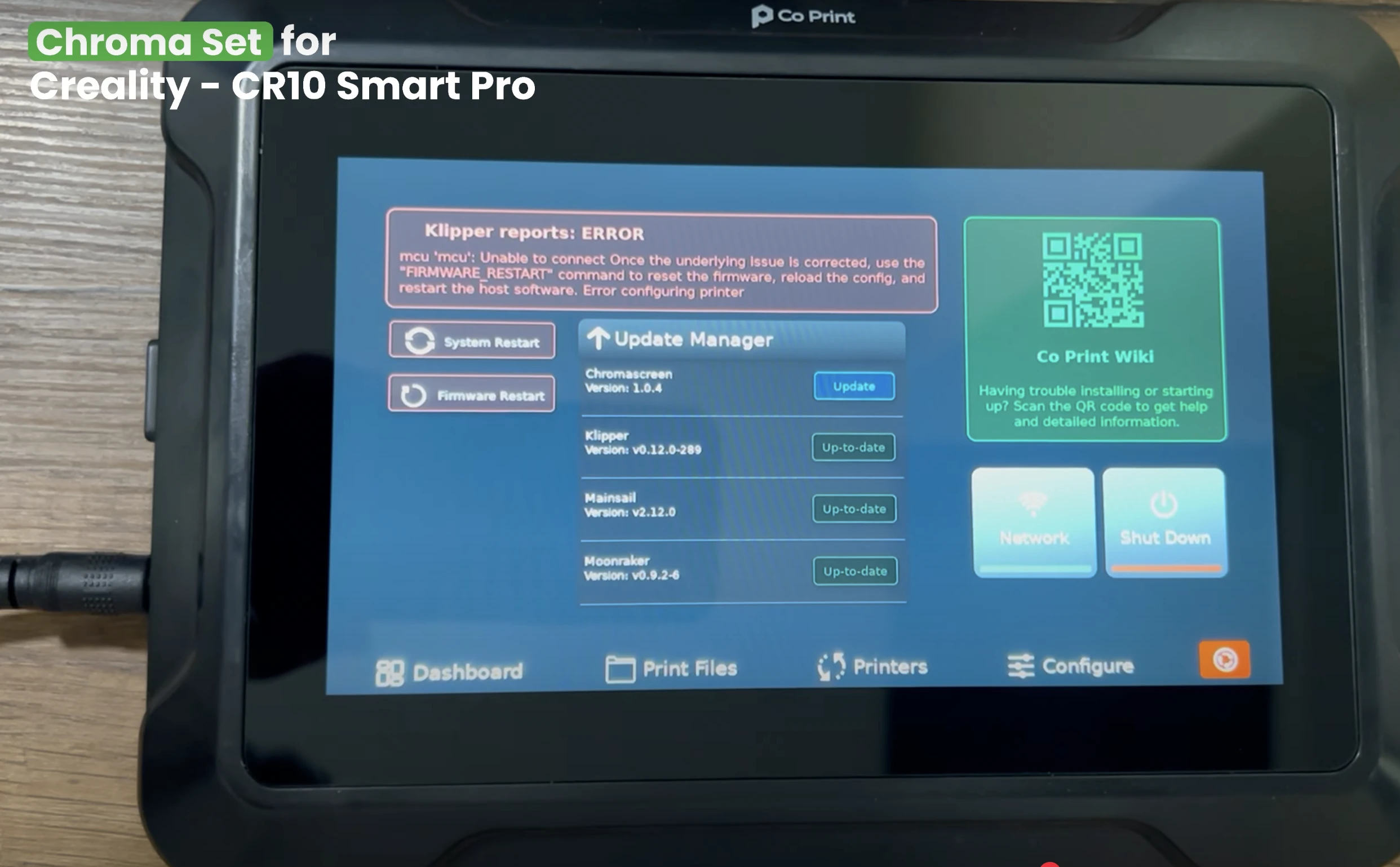
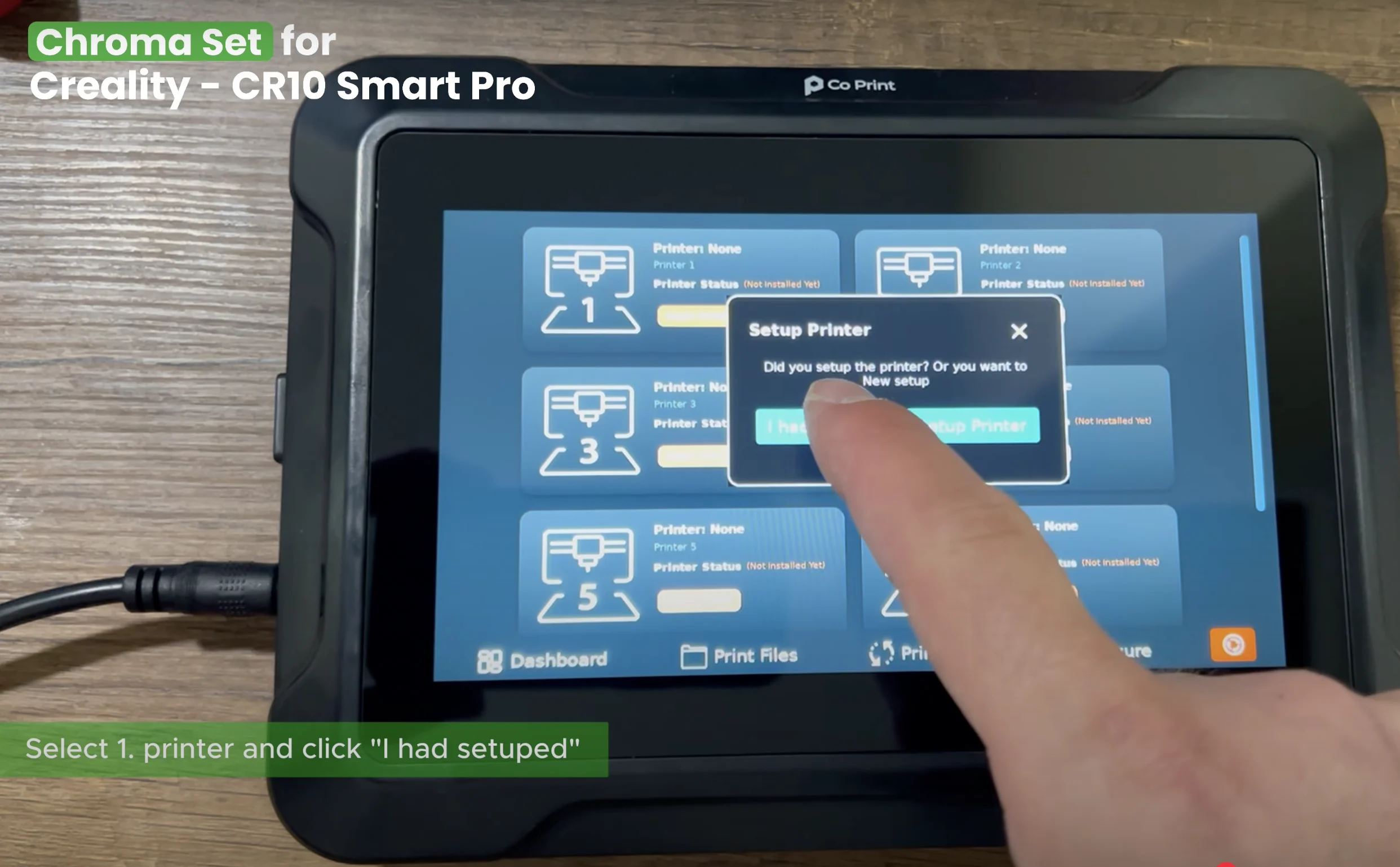
¶ 31- ChromaPad Setup
On the ChromaPad go to printers, selecet 1. printer and click "I had setuped".
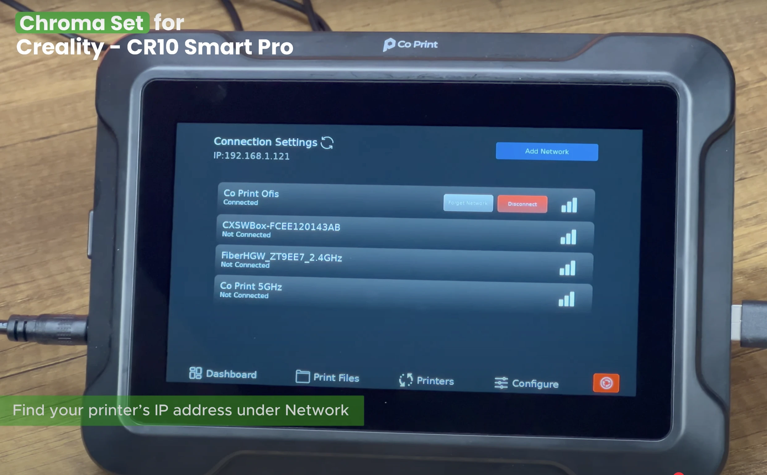
¶ 32- Open Mainsail
Find your printer's IP address under Network and enter the IP address in your browser to open Mainsail.
¶ 33- Upload the Configuration Files
Download the required files from GitHub and place them in the config folder at "MACHINE" Section of Mainsail.

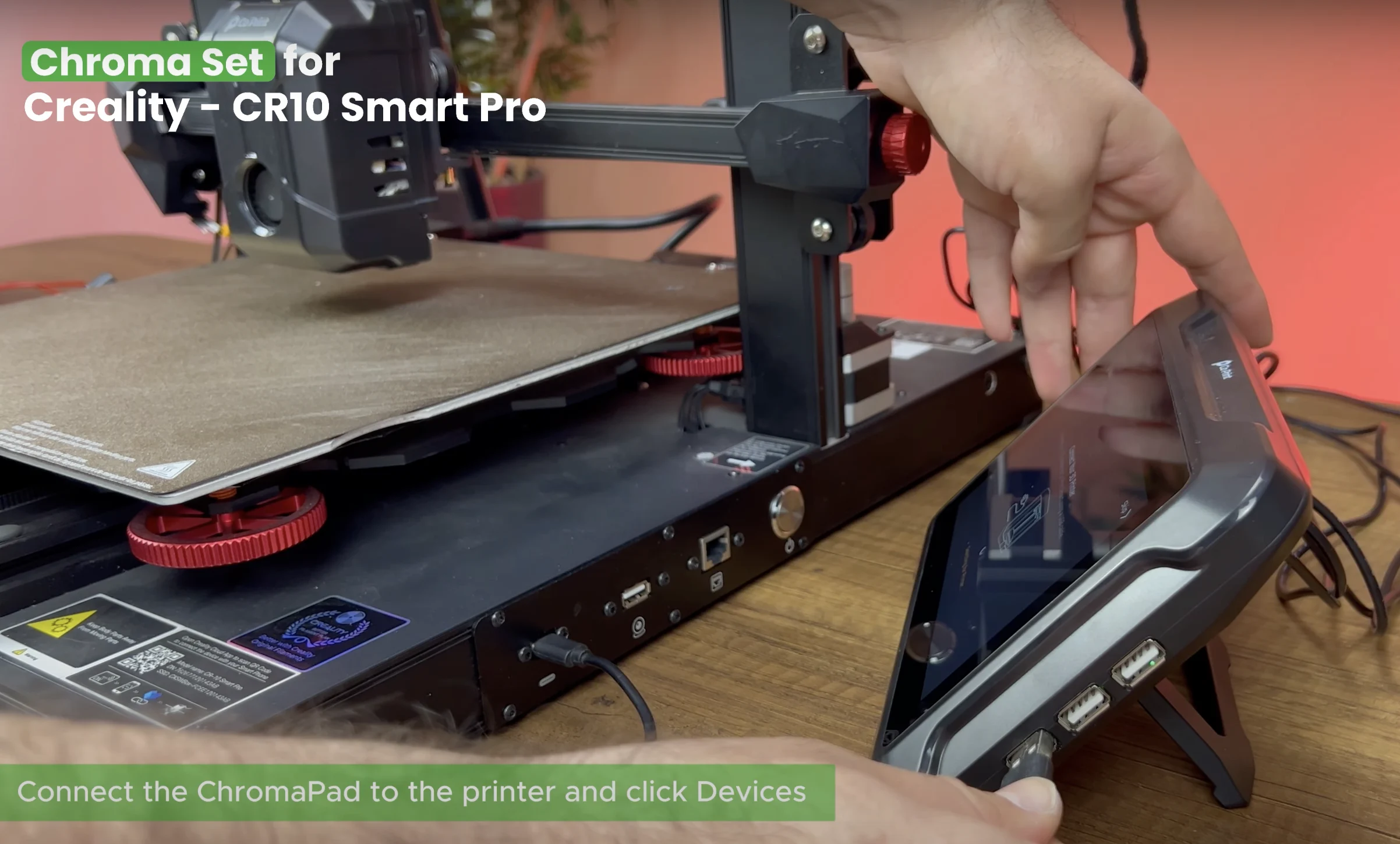
¶ 34- Connect the ChromaPad
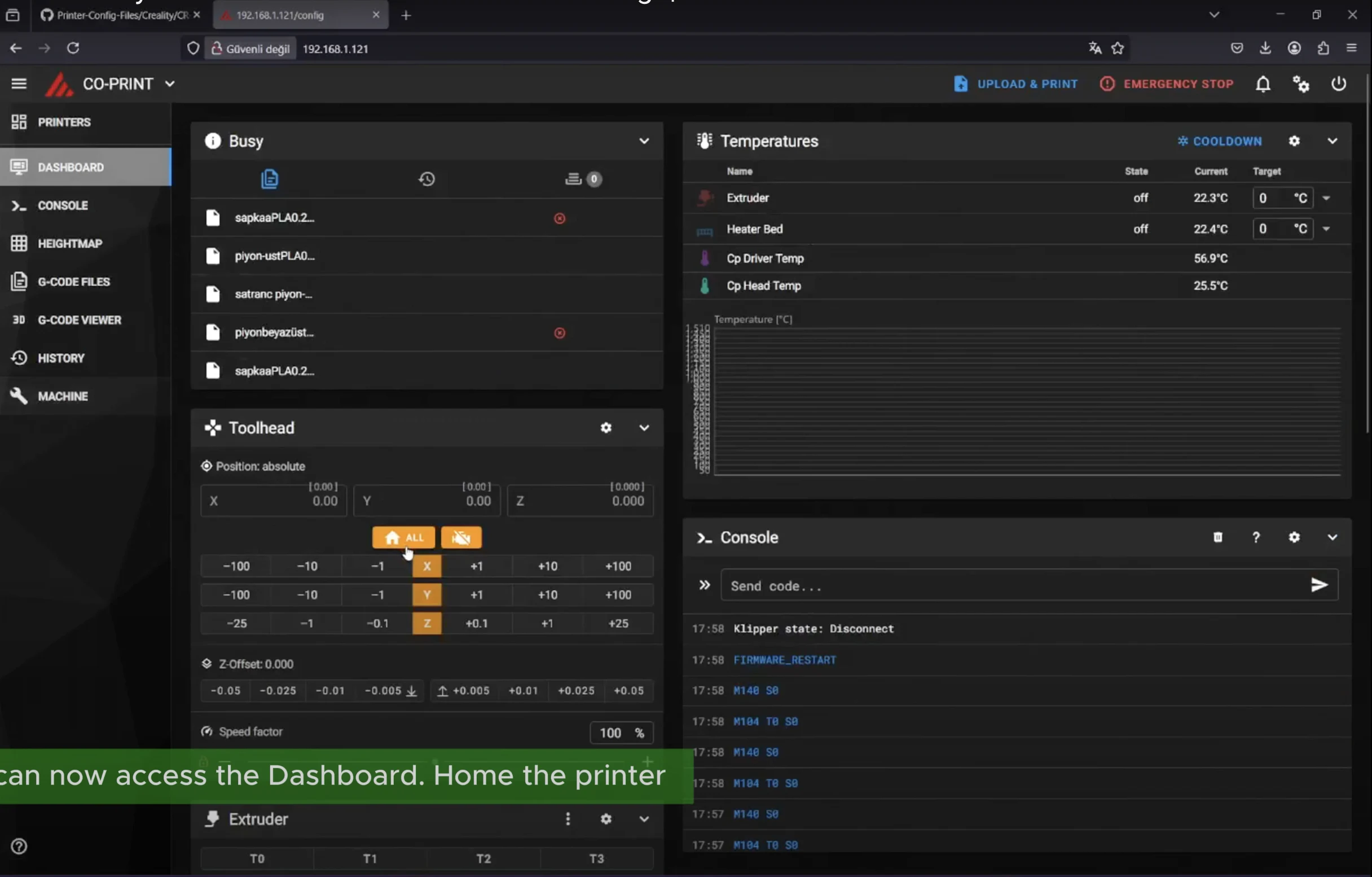
Open the printer.cfg file, connect the ChromaPad to the printer and click Devices. Click Refresh and find the ttyUSB path. Copy the path and paste it into the serial section then click "SAVE & RESTART". You can now access the Dashboard.
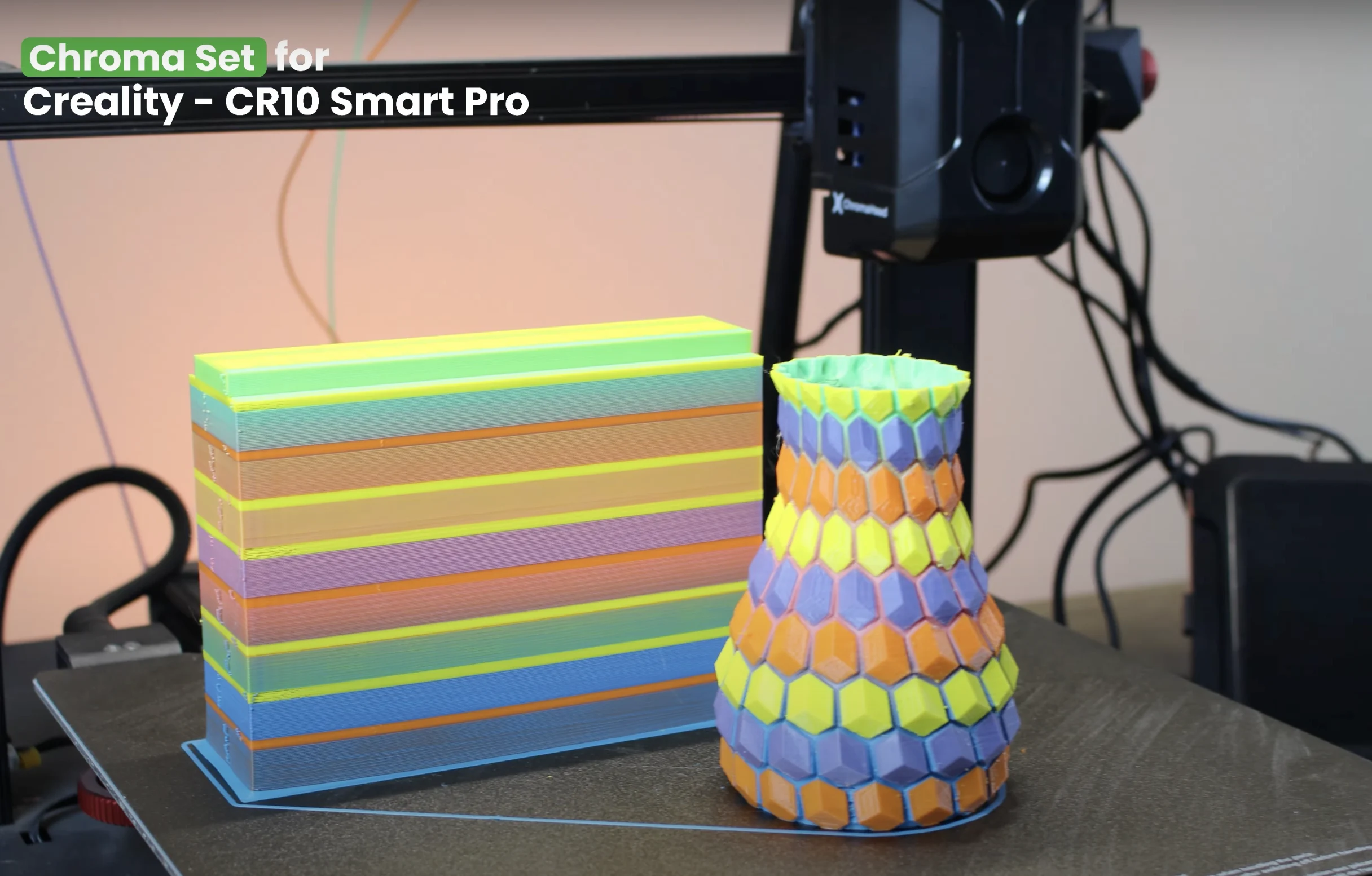
¶ 35- Start Printing
You can open Orca Slicer and load your model. Adjust the settings, paint the model and slice it. Your printer is ready to use.