¶ Ender 3-V3/Plus KCM Set Upgrade
| Image | Information |
|---|---|
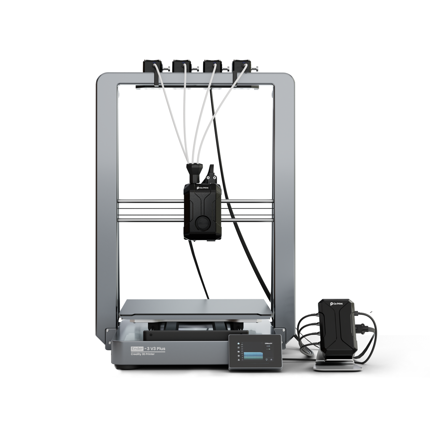 |
Welcome to the installation page for Ender 3-V3/Plus KCMSet. This guide will help you update your printer's firmware to ensure compatibility with KCMSet, download and print the required .STL files for mechanical assembly, complete the mechanical setup, and configure the Klipper settings. By following these steps, you will successfully complete the installation process. |
¶ Software Upgrade
Before starting the installation, you need to update your printer's firmware to the version officially provided by Creality, which is fully compatible with KCMSet products.
- Ender 3-V3/Plus Printer Firmware V1.2.3.30 Download
- Ender 3-V3/Plus Printer Firmware V1.2.3.63 Download
-Added support for Creality Ender-3 V3
-Fixed various bugs
¶ Downloadable parts required for the installation
| Image | Part Name | Links |
|---|---|---|
 |
ChromaHead Adapter Part | Download |
 |
CX-I Extruder Holder Kit | Download |
 |
KCM Holder | Download |
 |
ECM Holder | Download |
¶ Klipper Config Files for KCM Set
¶ 1- Upgrade the Printer Firmware
- Make sure to download the latest Ender 3v3 Color Printing firmware from the link provided above.
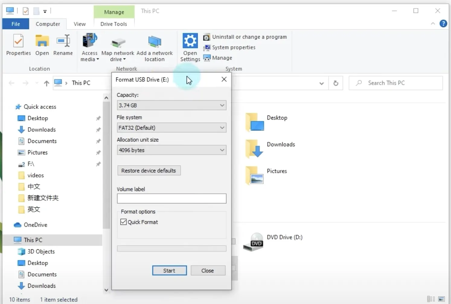
- Prepare a USB flash drive with at least 4GB of storage.
- Insert the USB flash drive into your computer and format it with the File System set to FAT32 and the Unit Size set to 4096Bytes.
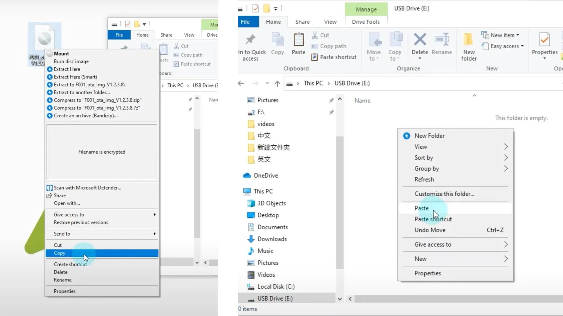
- Then, copy the downloaded .img extension ISO file and paste it into the flash drive.
- Click the eject option to safely remove the flash drive from your computer.
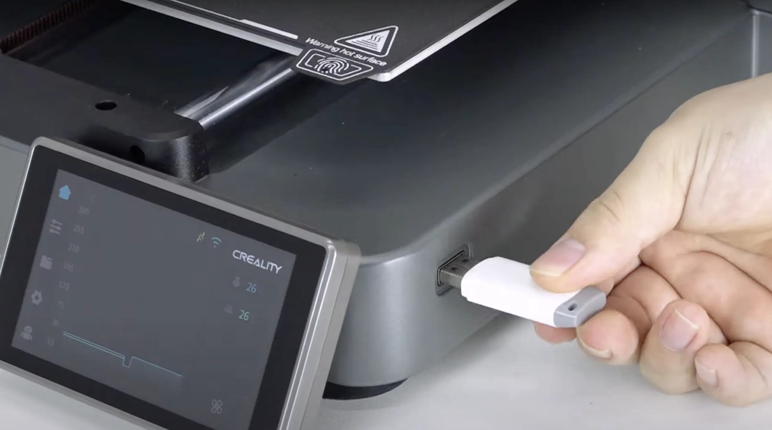
- Go to your Ender 3V3/Plus printer, and while the printer is powered on, insert the flash drive into the USB port.
- Click the Upgrade button in the popup that appears on the printer's screen.
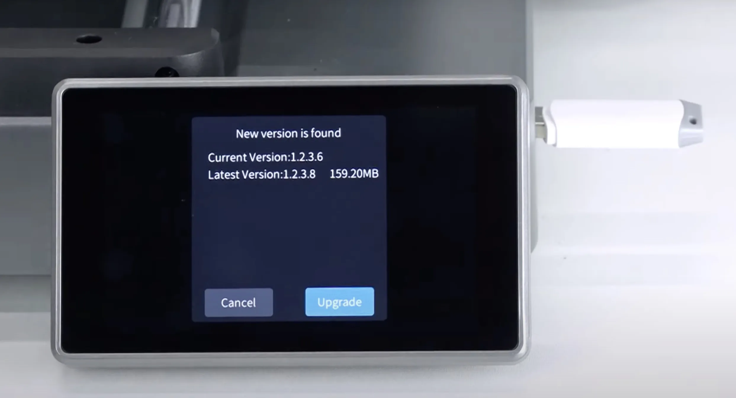
- Do not turn off the printer and do not remove the USB drive until the update is complete.

- After the update is complete, make sure that the installed version is V1.2.3.30.
¶ 2-Remove the Stock 3D Printer Toolhead
- Pull the plastic cable protector upwards by holding it from the top and remove it.
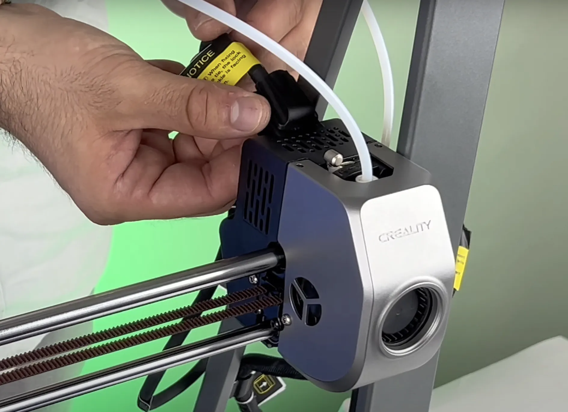
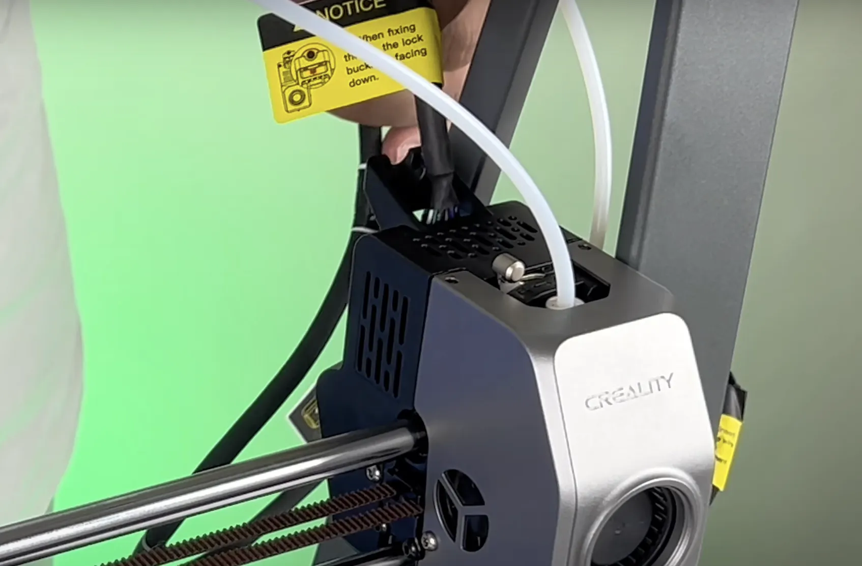
- Disconnect the stock toolhead's connection cable from its socket.
- Remove the two Allen-headed screws on the left side of the toolhead.
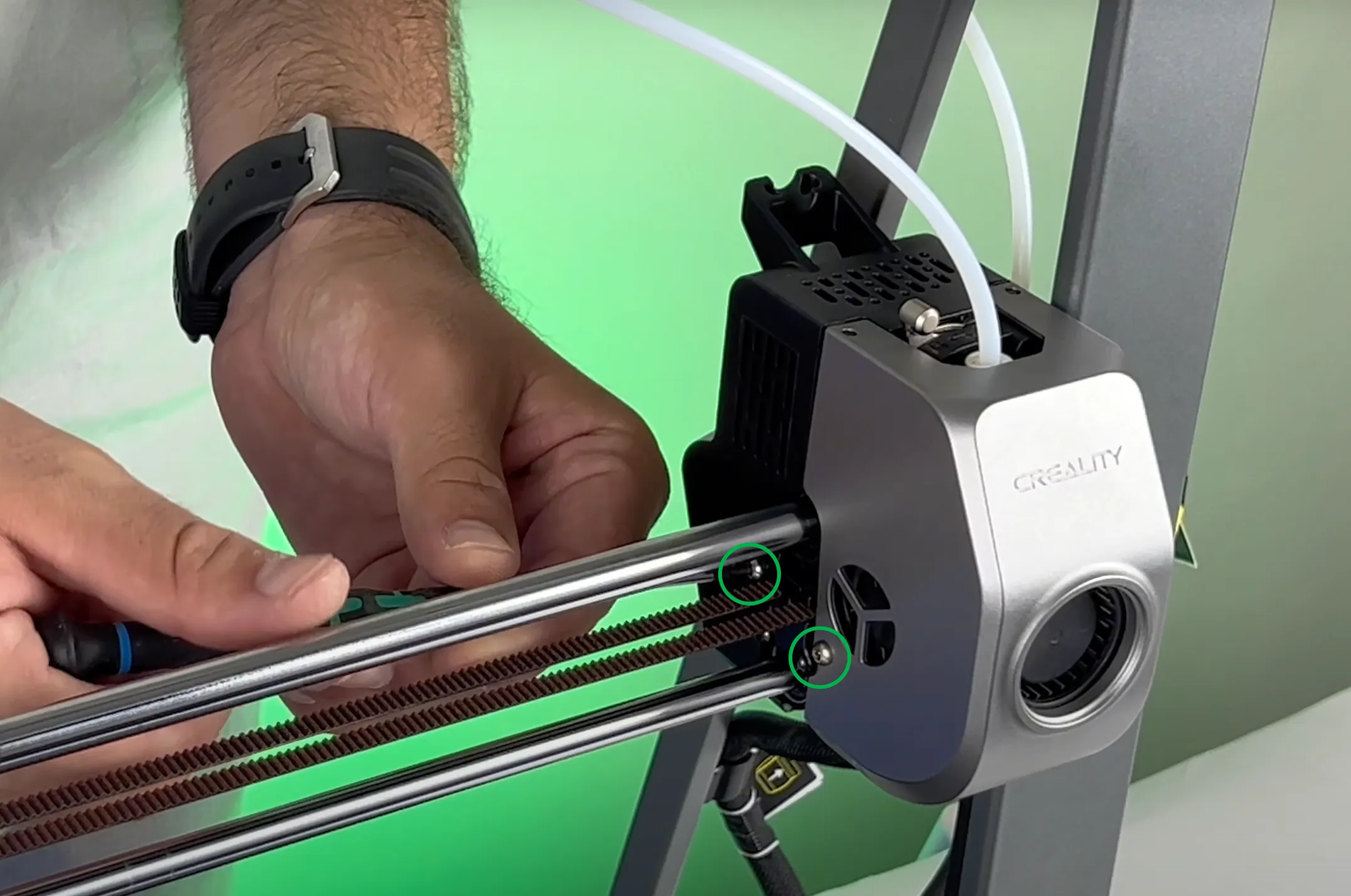
- Remove the two screws on the right side.
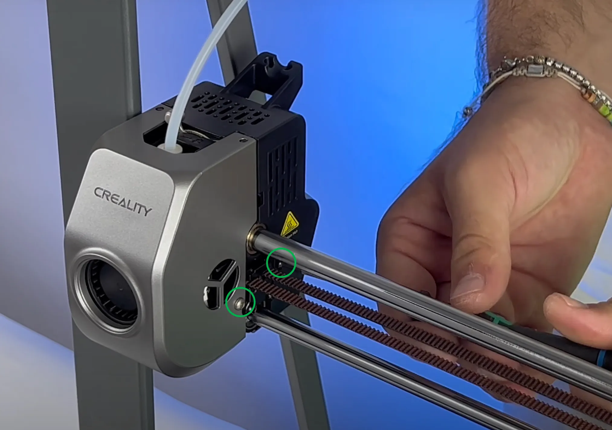
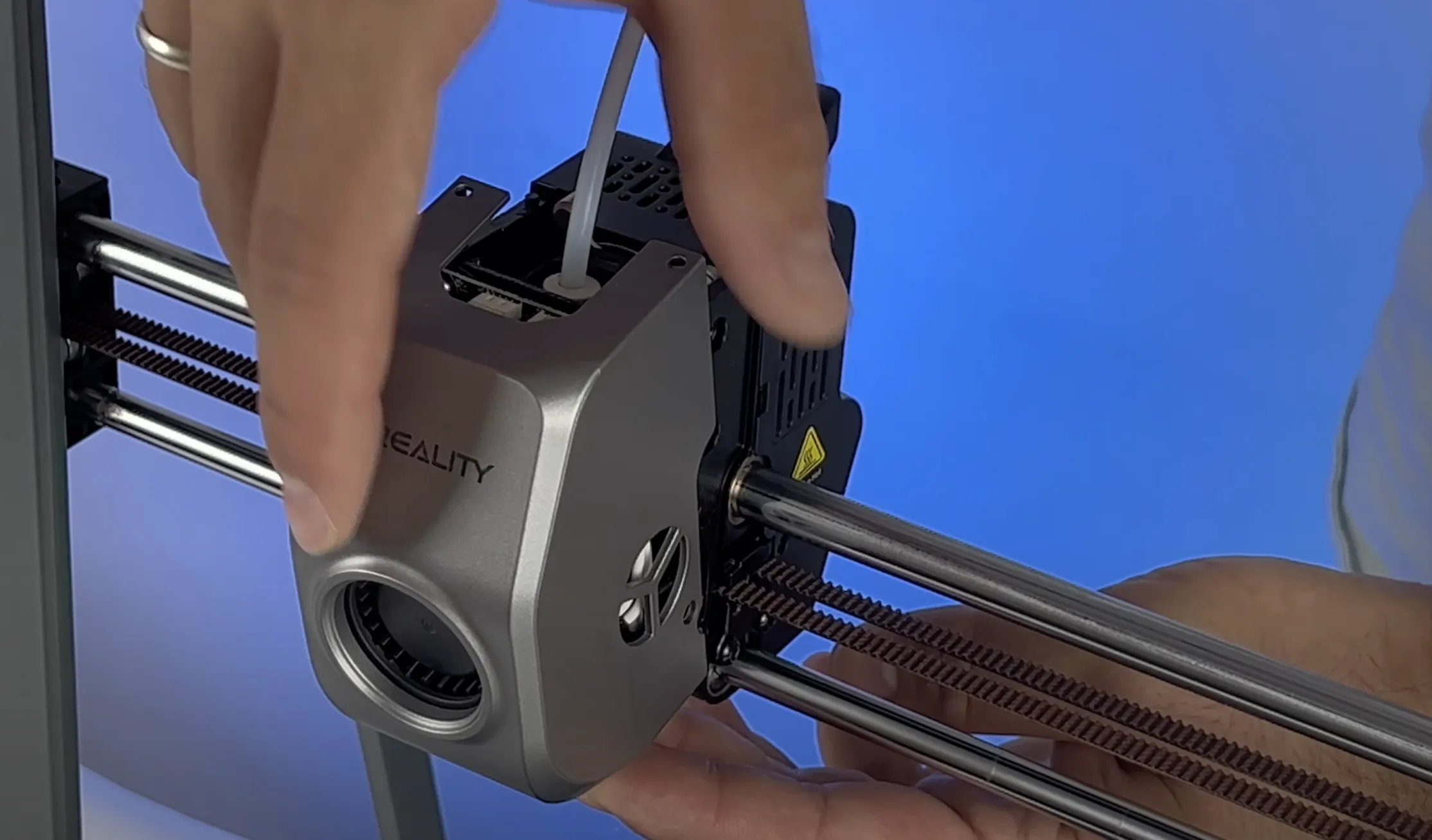
- Remove the front cover.
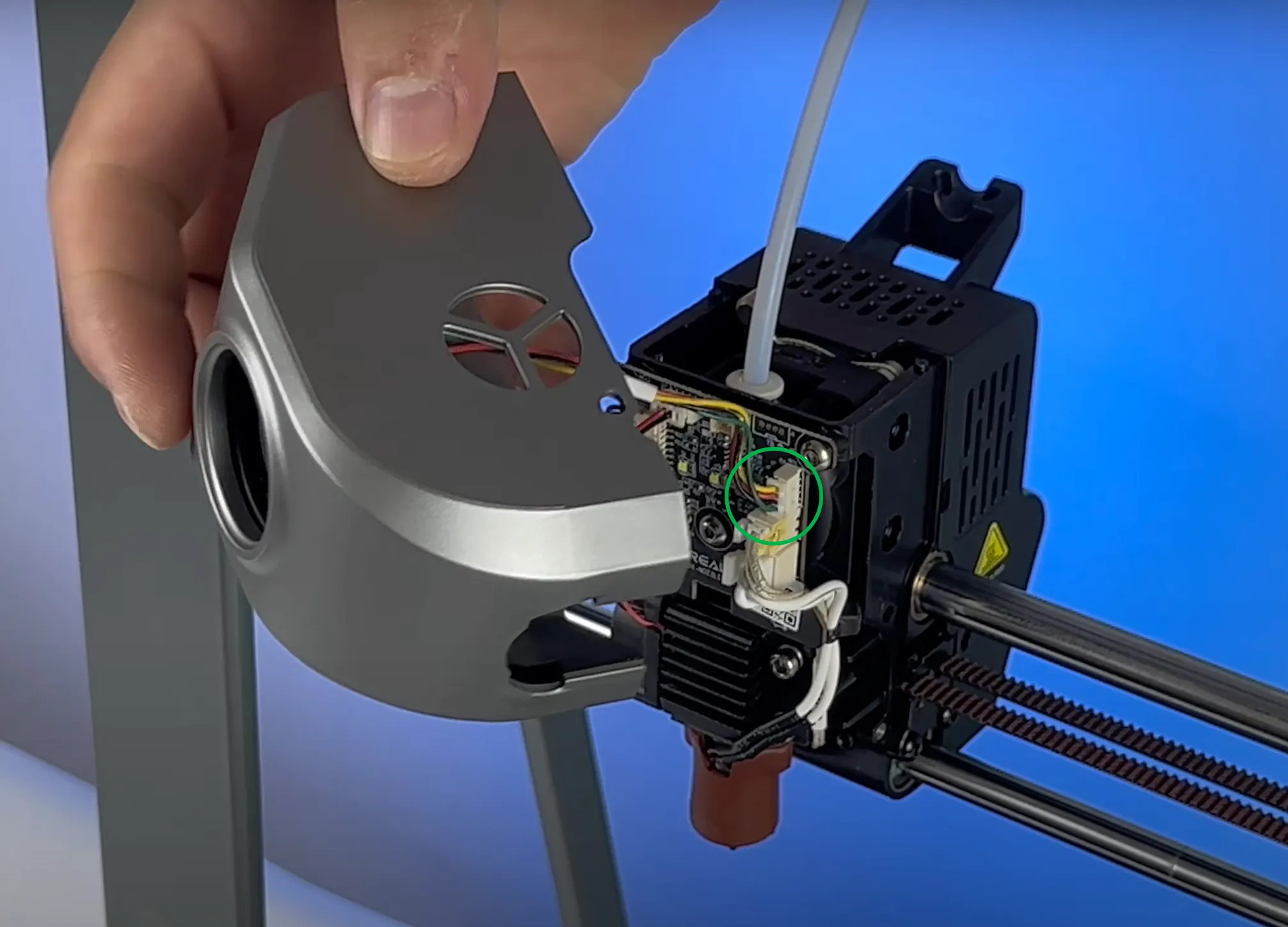
- Disconnect the front cover's socket from the control board.
- Push the extruder latch to the right to open it.
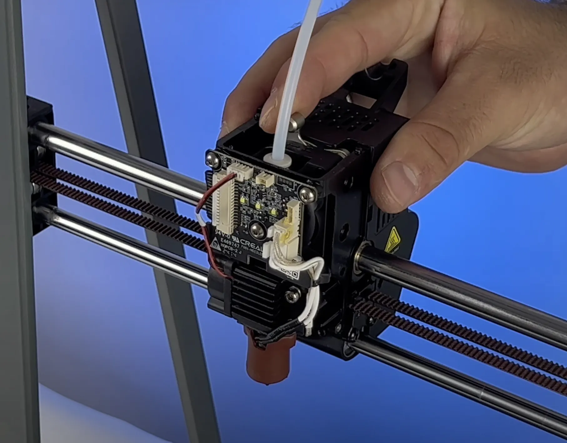
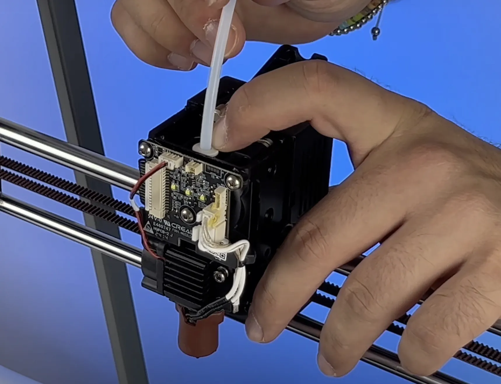
- Press the PTFE tube into the white holder and pull it out.
- Remove the two screws on the right side.
- Remove the one screw on the left side.
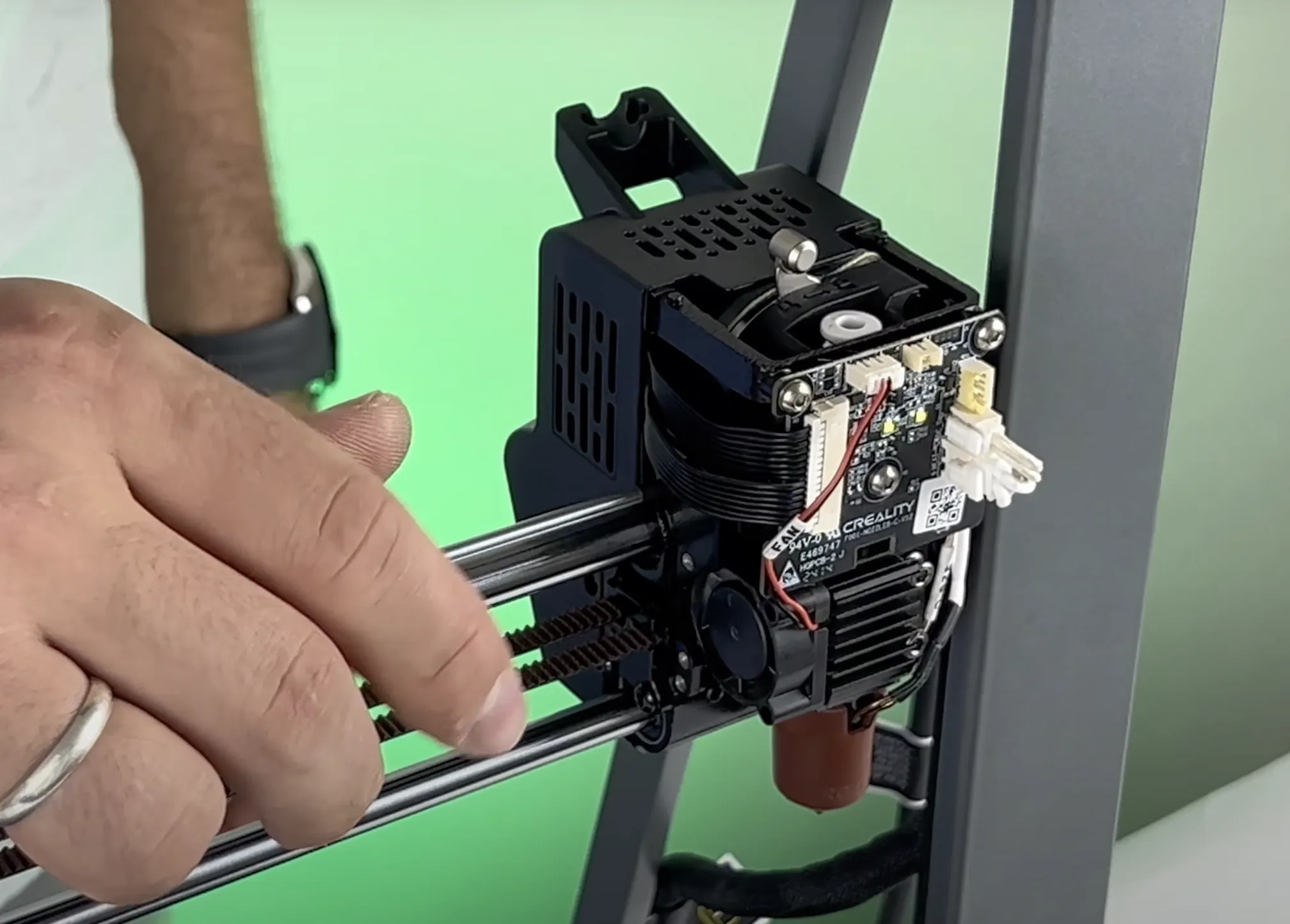
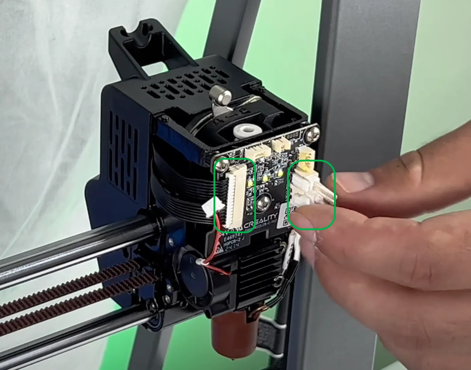
- Disconnect all the cables from the control board.

- Remove the three screws on the control board.
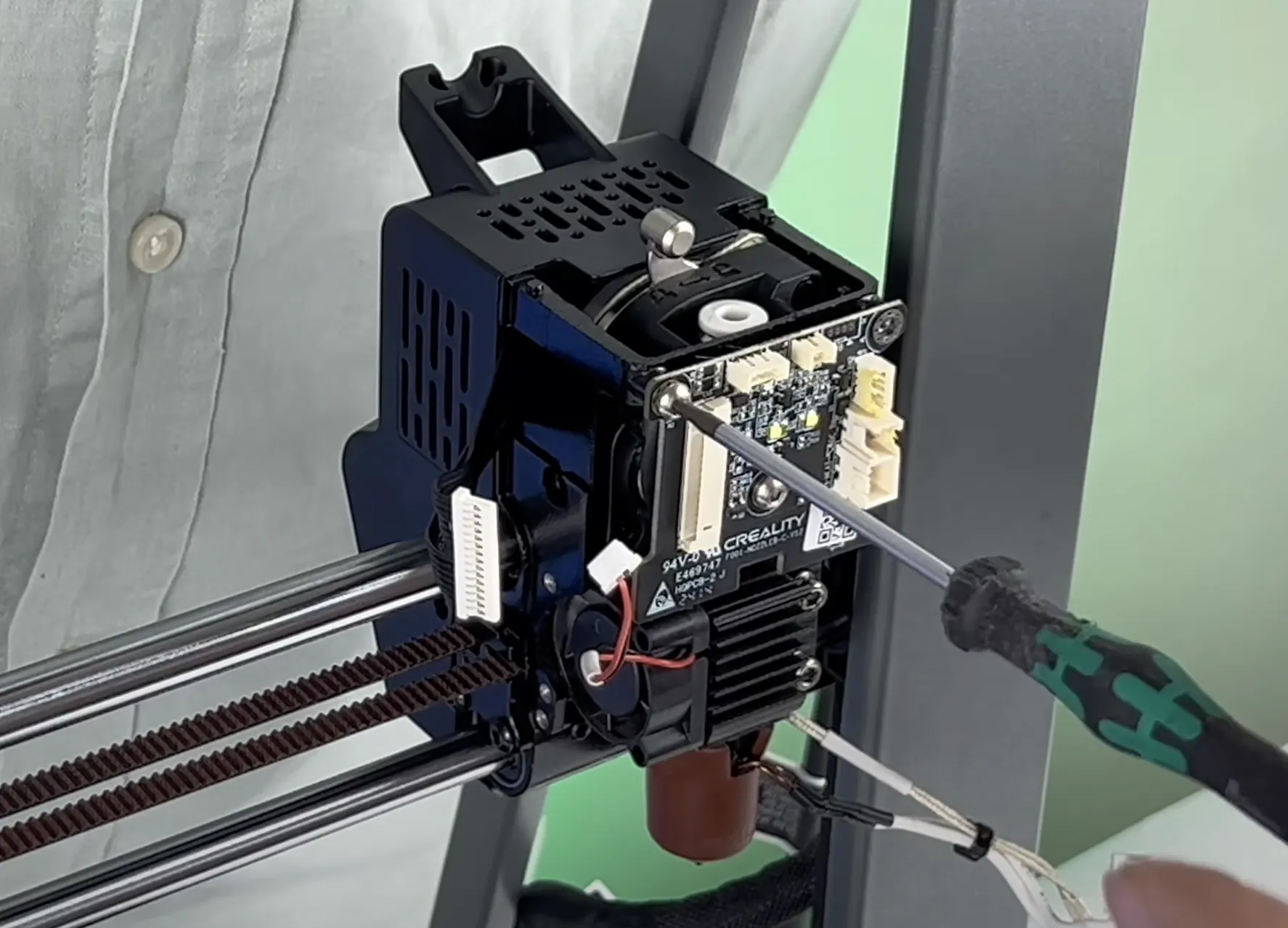
- Remove the two screws on the back of the toolhead.
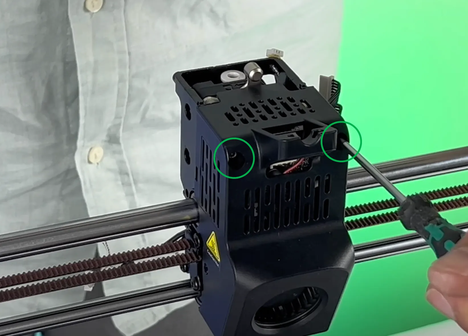
- Remove the rear cover.
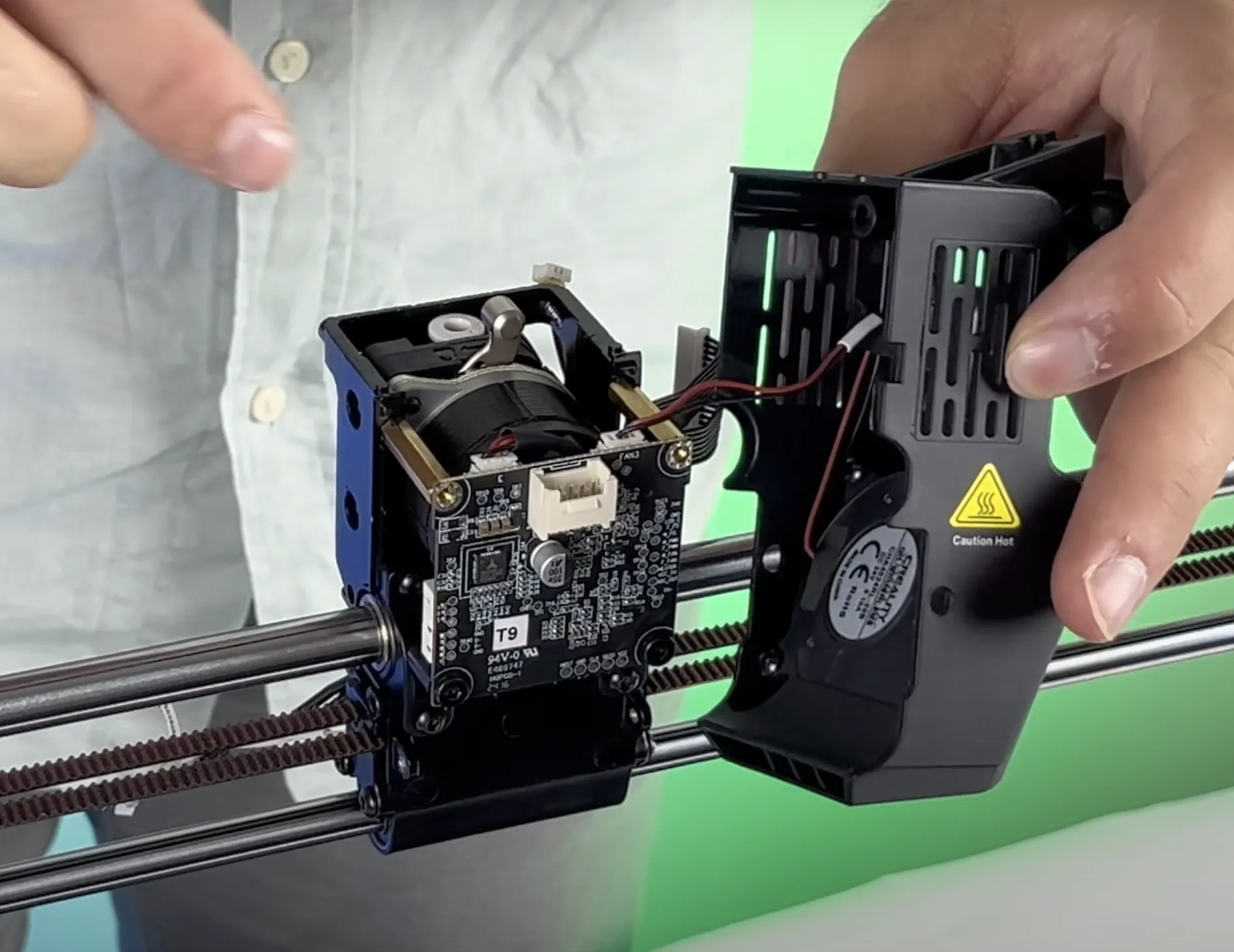
- Disconnect the socket of the fan connected to the rear cover.
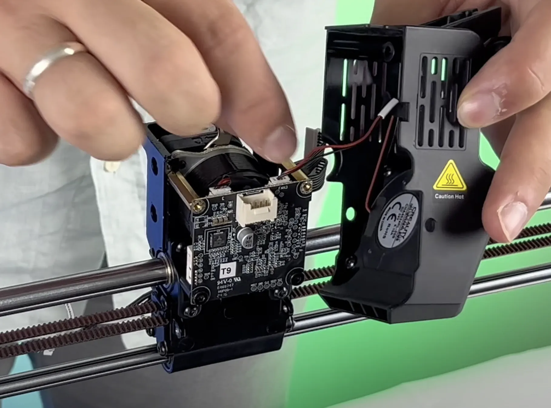
- Remove the screws from the rear control board.
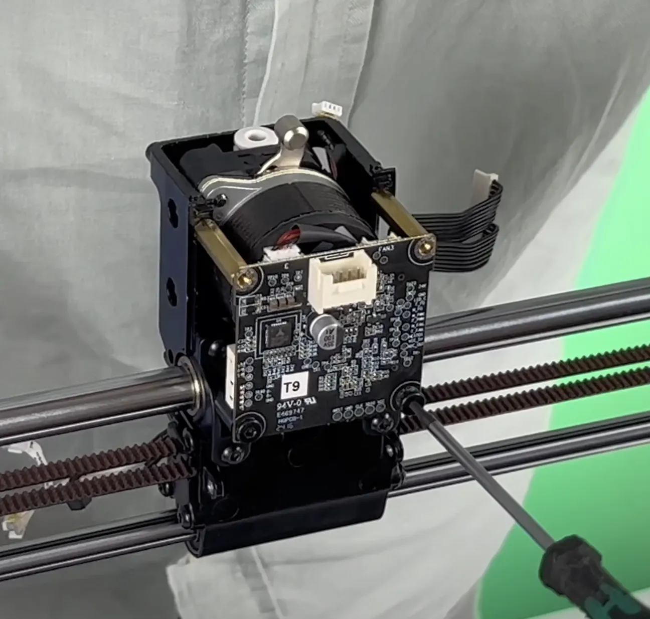
- Disconnect the socket connection on the rear control board.
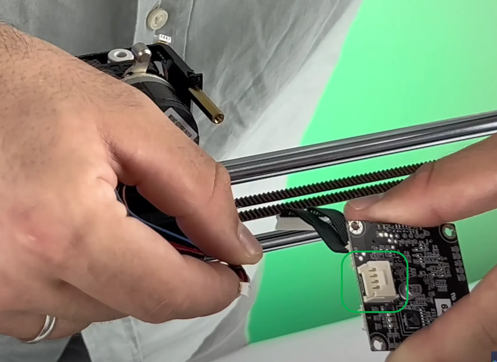
- Pull the pancake motor upwards to remove it.

- Remove the screws holding the hotend on the front of the head.
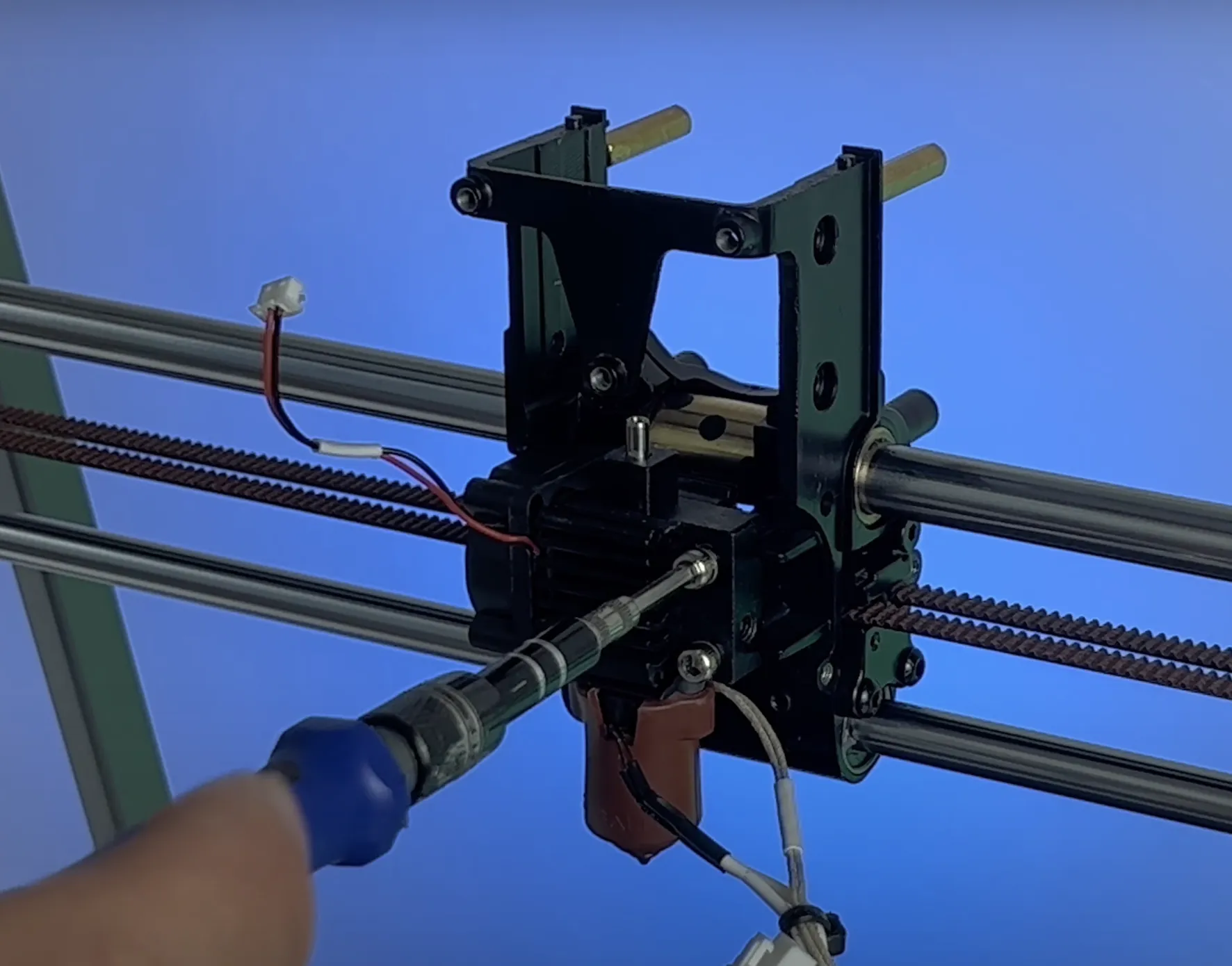
- Remove the hotend from its position.
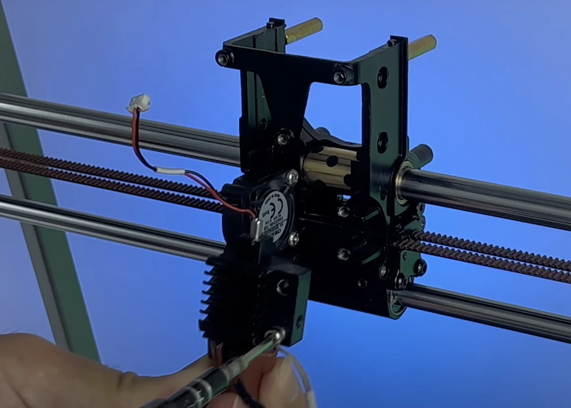
- Remove the fan screws and take the fan out of its position.
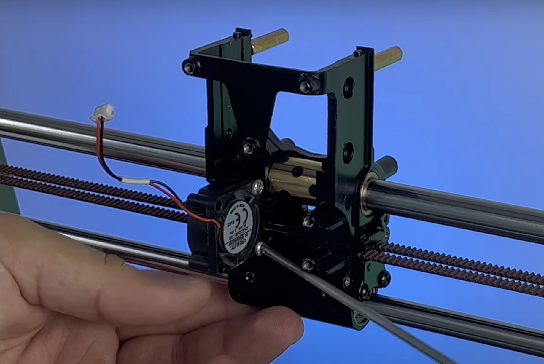
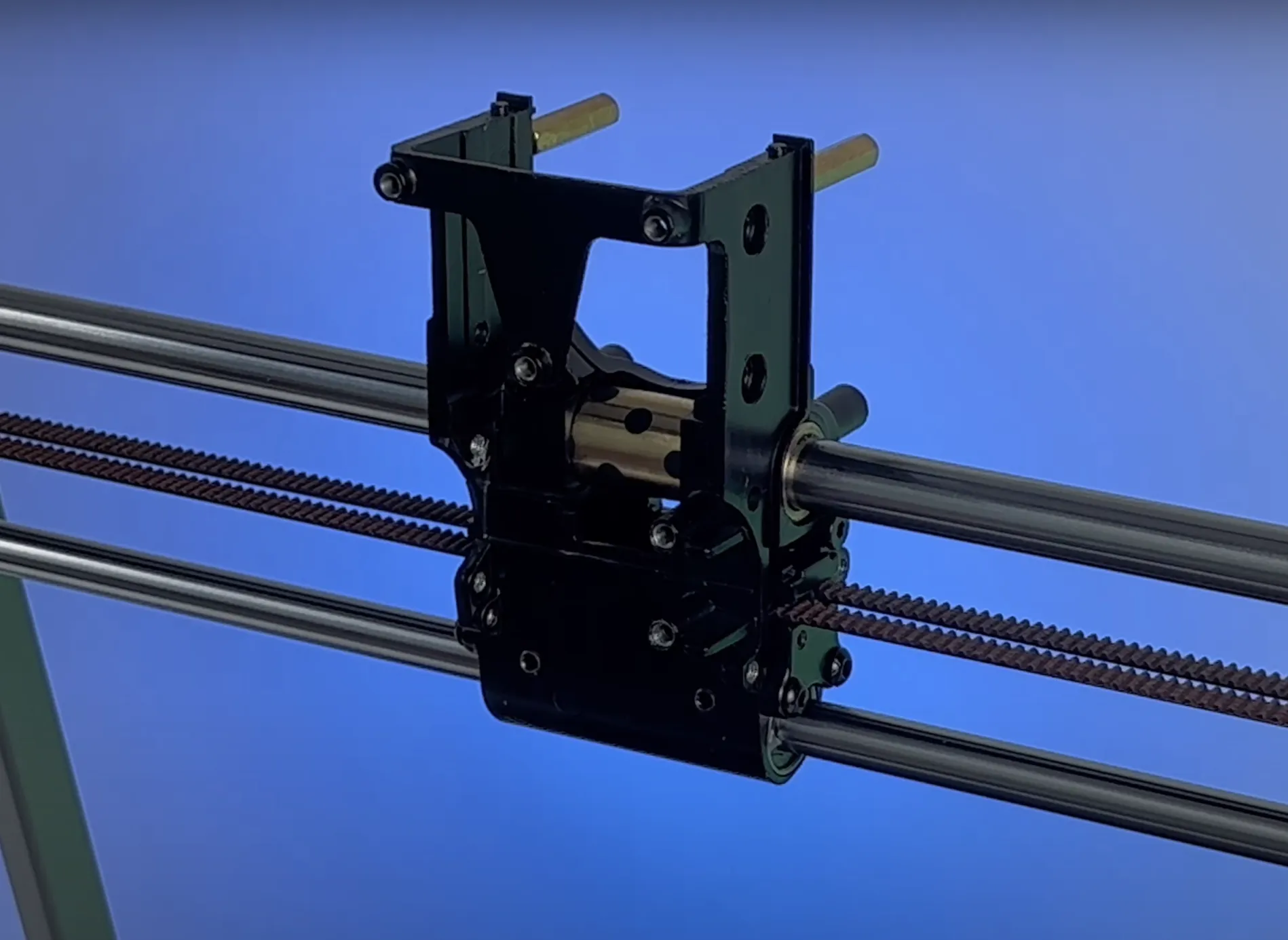
- Complete the disassembly, leaving the part below.
¶ Mechanical Setup
-
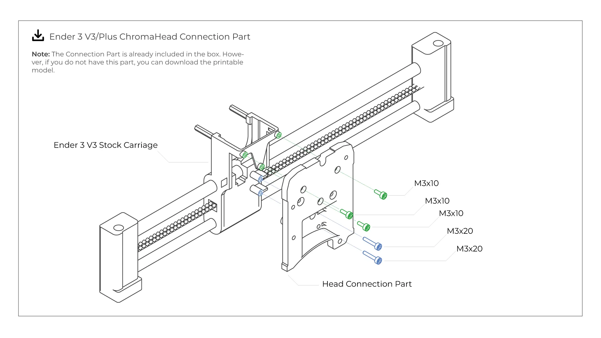
Mounting the Connection Part
Align the ChromaHead mounting part with the stock carriage on the Ender-3 V3 and insert the screws as specified below. Ensure that the part is securely fitted and does not wobble.
-
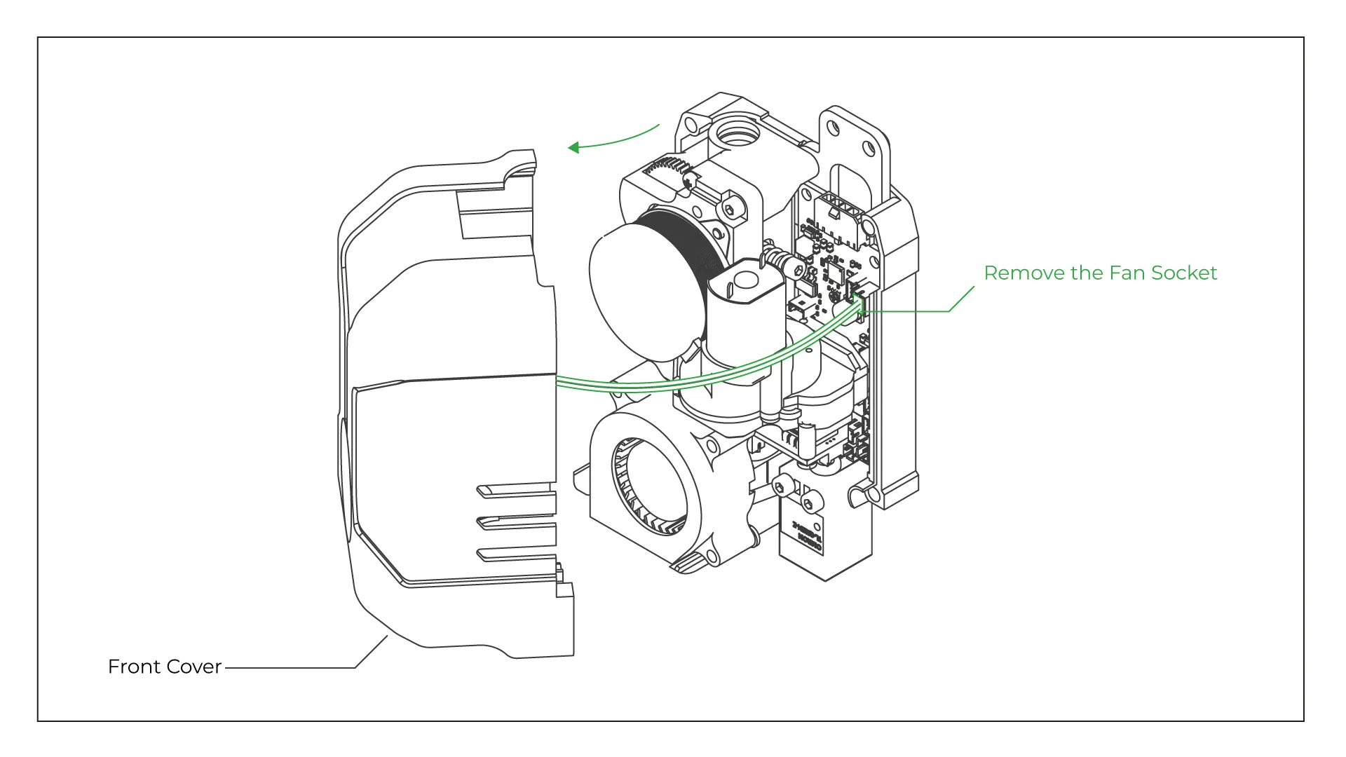
Remove the front cover of the ChromaHead
Align the ChromaHead mounting part with the stock carriage on the Ender-3 V3 and insert the screws as specified below. Ensure that the part is securely fitted and does not wobble.
-
Plug the ChromaHead to the Connection Part
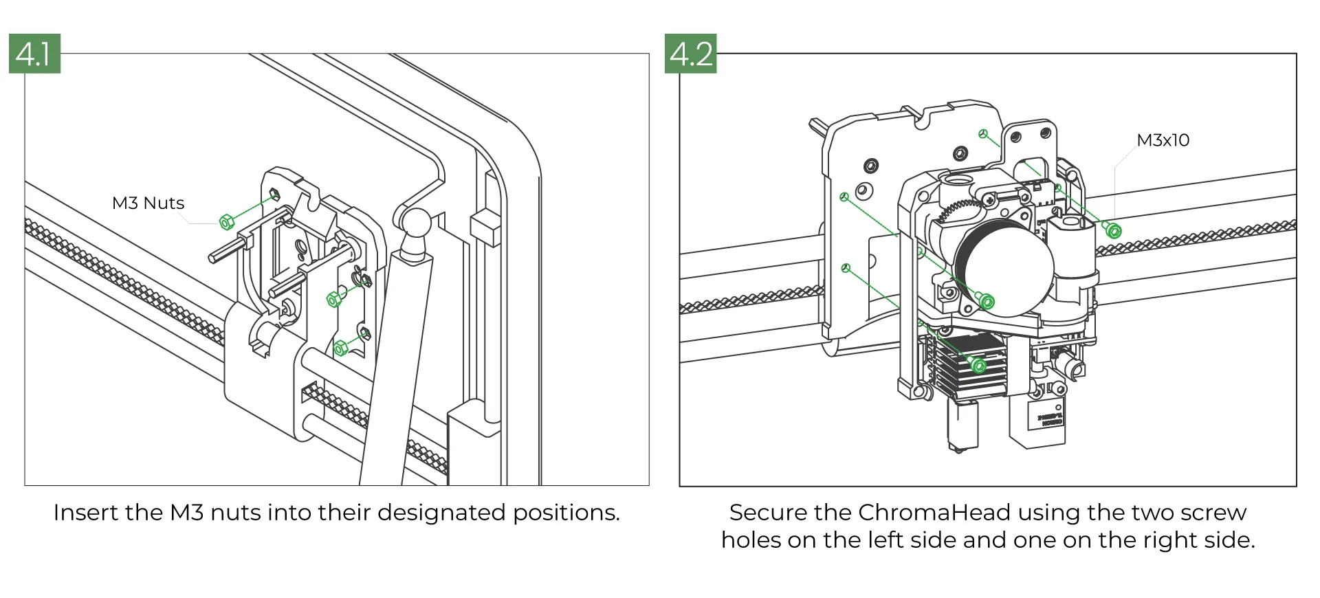
First, insert the M3 nuts into the nut holes on the back of the Connection Part as shown in Step 4.1. Then, align the ChromaHead (with the front cover removed) with the holes and secure it using M3x10mm screws as illustrated in Figure 4.2.
-
Plug the ChromaHead Cable, 8in1 Module
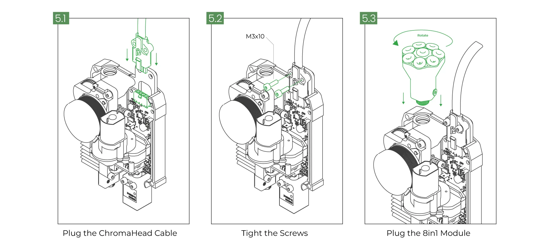
Insert the specially designed ChromaHead connection cable from the box into the socket. Then secure it using M3x10mm screws. As the third step, rotate the 8-in-1 module into place and slide it onto the PTFE holders.
-
Close the ChromaHead’s Front Cover
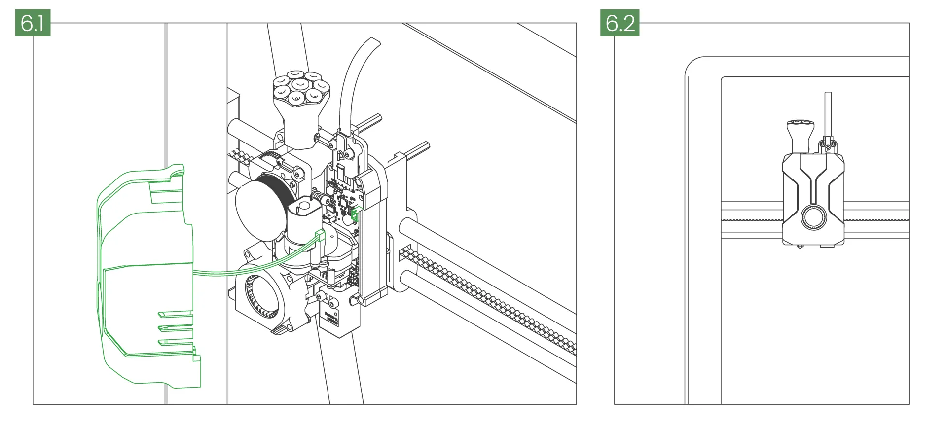
As the final assembly step for the ChromaHead, connect the fan cable on the front cover to the specified socket. Then, close the front cover. In the second step, once the ChromaHead installation is complete, you can see the correct positioning.
-
Mount the Extruder Carriage Part
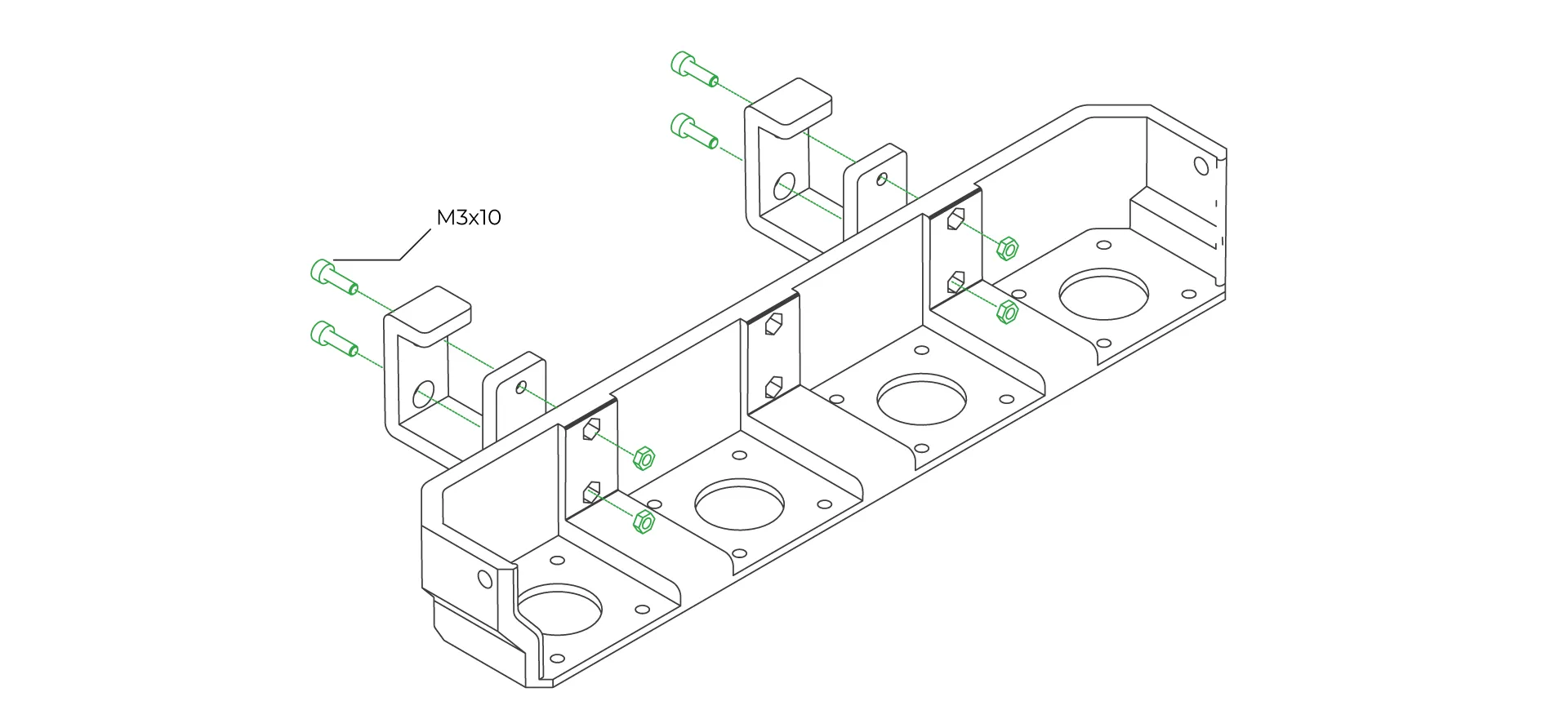
Place the nuts into the nut slots inside the 4-extruder holder included in the box. Then, align the hook feet with the holes and secure them using M3x10 screws.
-
Attach The 4-Extruder Holder to The Printer
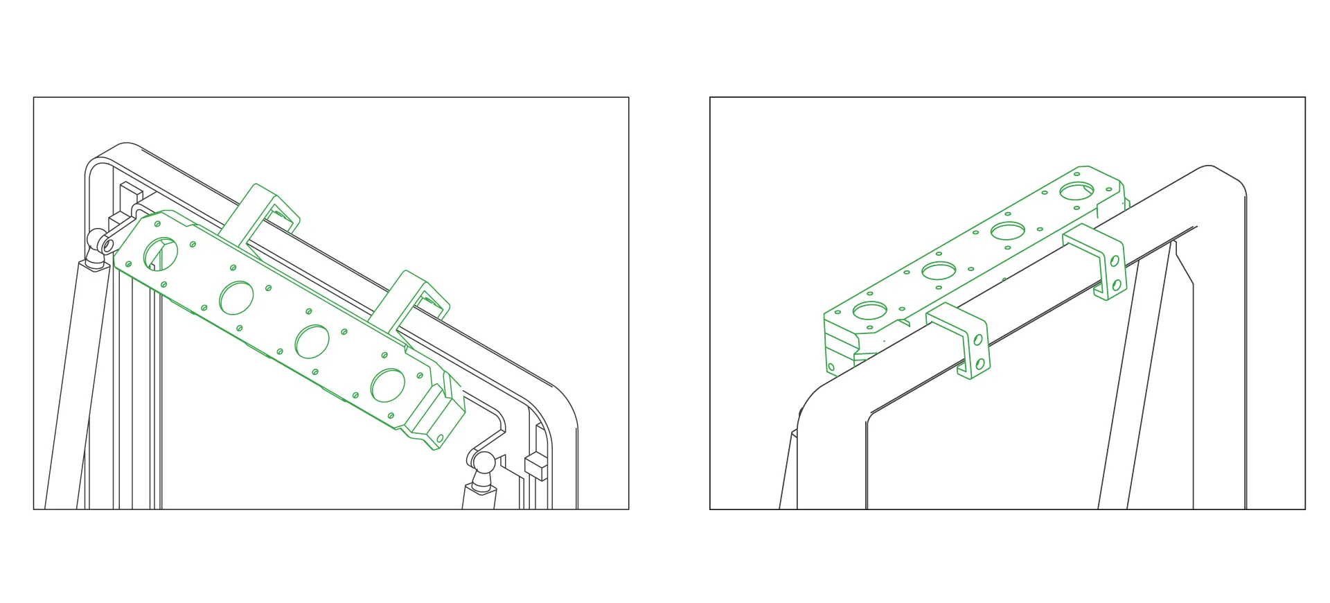
Slide the 4-extruder holder onto the profile using the hook feet. To make it easier to attach, tilt the piece towards the back of the printer, as in the first step.
-
Mounting CX-I Extruders for 8 Filament Pack
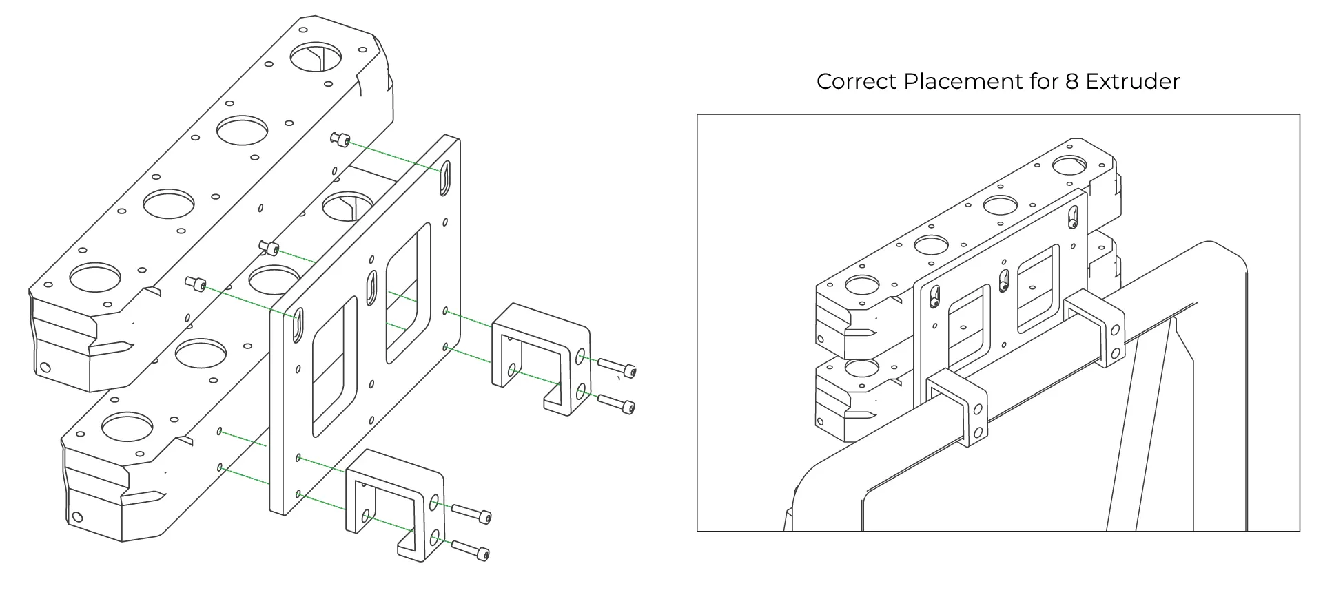
If you have purchased the KCM Set eight-extruder package, you can use the additional connectors provided in the box to attach 8 extruders instead of 4. Secure the lower 4-extruder holder using the screws that pass through the hook feet, and mount it onto the rail mechanism using the screw holes located in front of the filament holder at the top.
-
Mounting CX-I Extruder
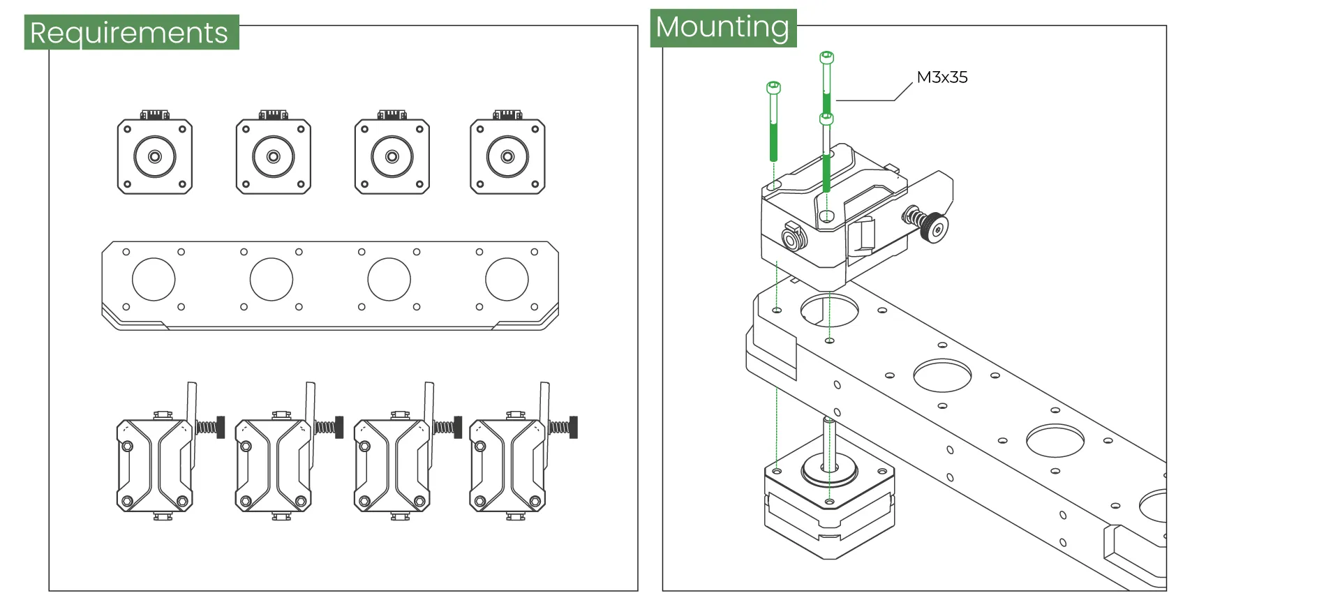
Place the extruders onto the 4-extruder holder included in the box as shown in the diagrams, and secure them with screws. Ensure that the cable sockets of the stepper motors are facing the back.
-
Attaching the PTFE Tubes
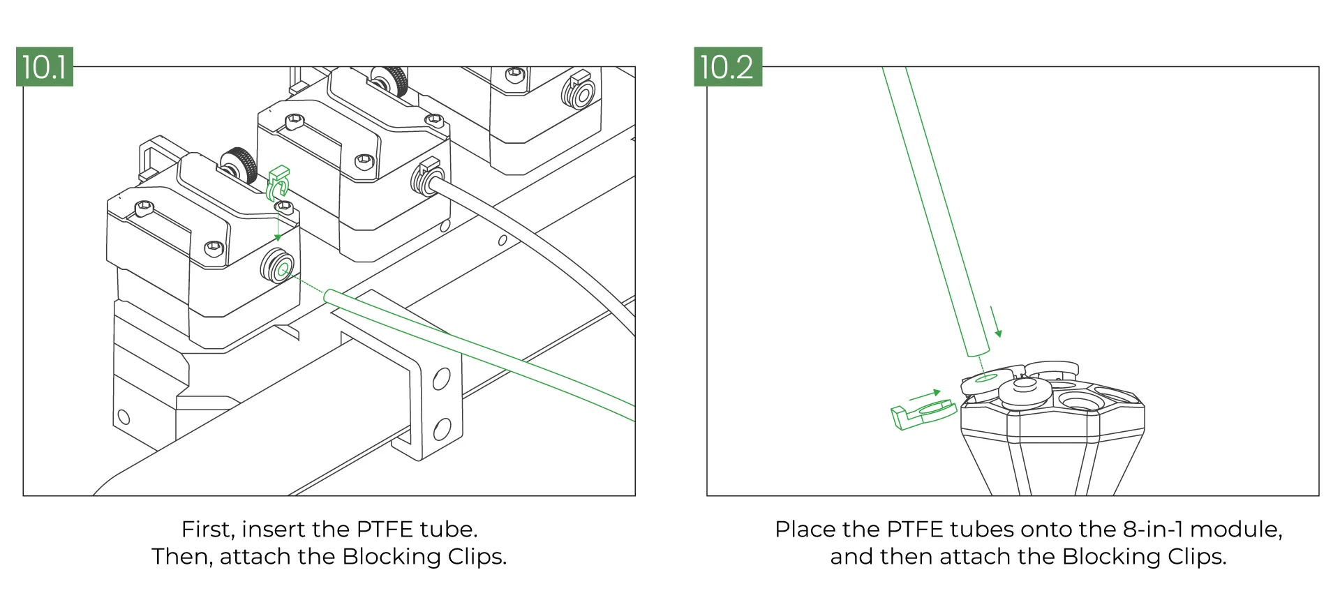
Attach one end of the PTFE tubes, which are customized according to the printer's size, to the CX-I Extruder and the other end to the PTFE holders on the 8-in-1 module. Then, secure them using the Blocking Clips.
-
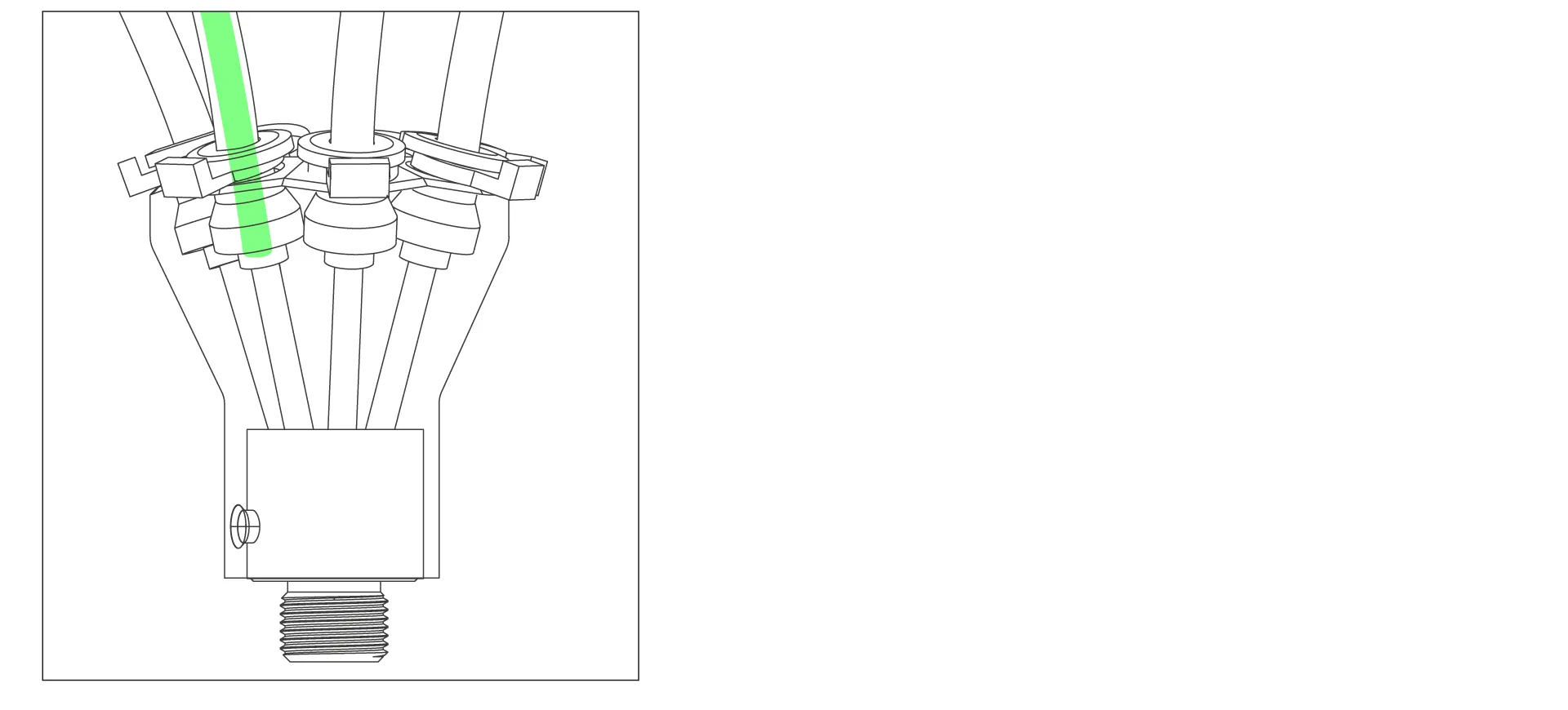
Positioning the Filaments on the 8-in-1 Module.
The ends of the filaments must be positioned inside the 8-in-1 module as shown in the image. This positioning is very important.
-
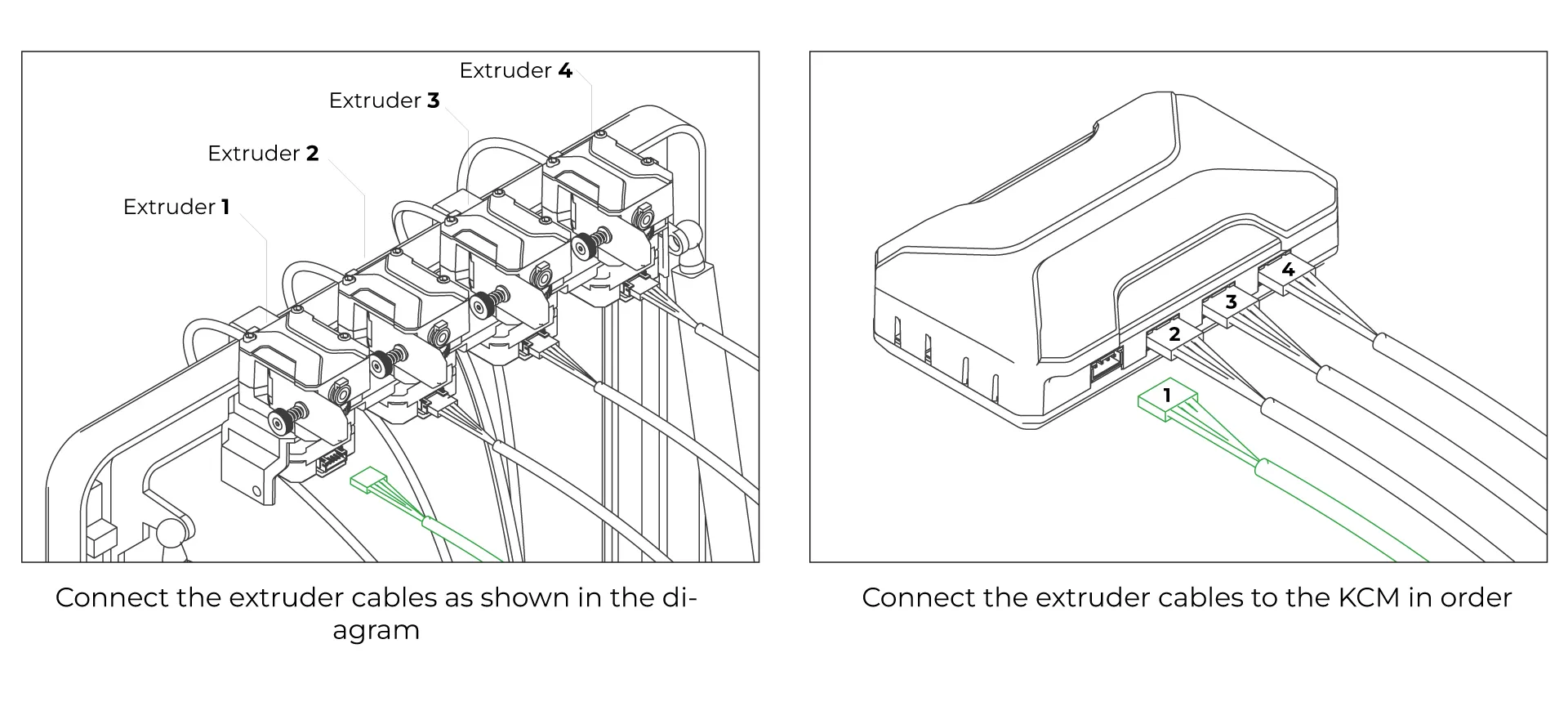
Connect the Extruder Motor Cables
Connect the extruder motor cables to the slots on the KCM in the order specified below. Always connect the cables before powering on the KCM. Do not plug or unplug cables after the KCM is powered on!
-
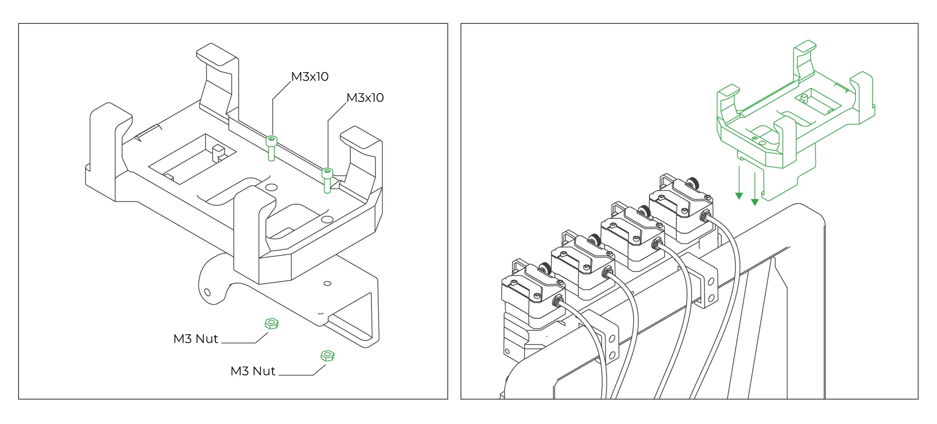
Assemble the KCM Stand
To position the KCM on top of the 3D printer and organize the cables, assemble the KCM stands. Attach the two pieces together using M3x10mm screws and M3 nuts, then slide the stand onto the profile as shown in Step 2.
-
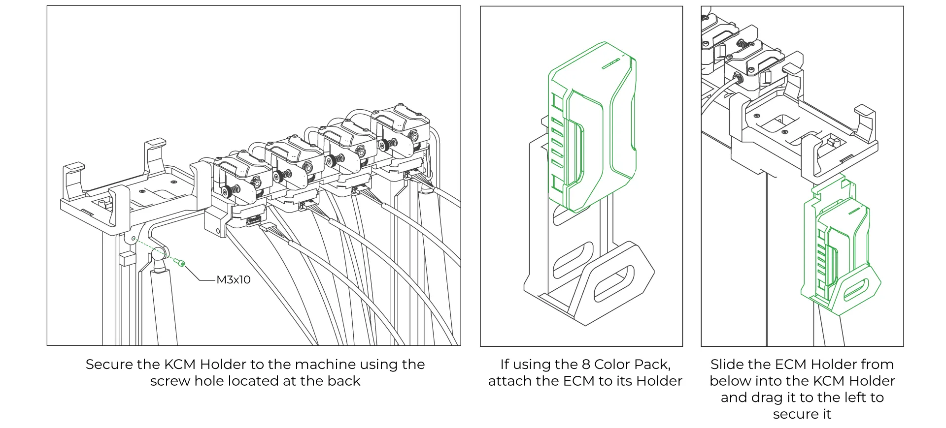
Assemble the KCM and ECM Stands
Connect the extruder motor cables to the slots on the KCM, following the sequence specified below.
-
Place the KCM and Connect its Cables
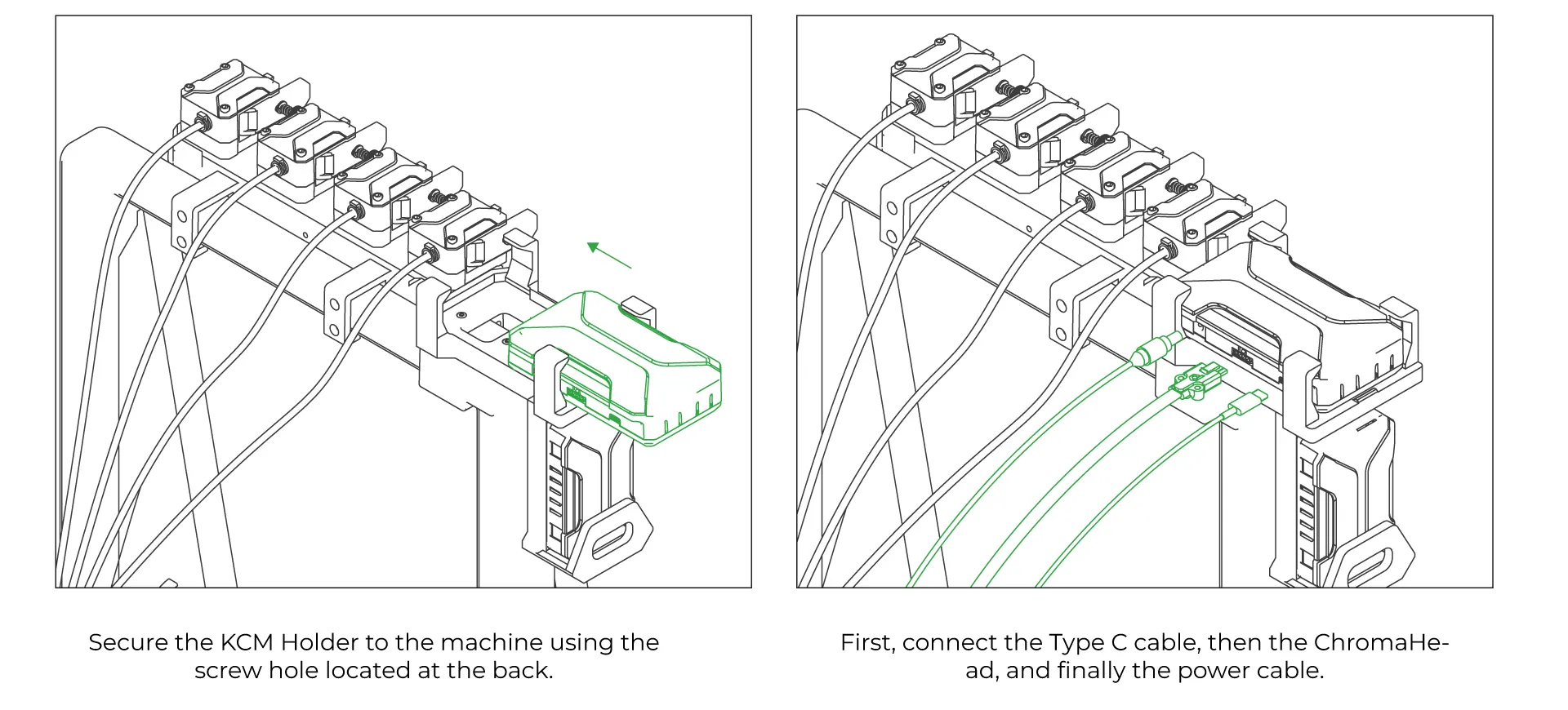
Slide the KCM into the custom-designed part to install it. Then, connect the Type-C, ChromaHead, and Power cables to the KCM in sequence.
-
Connect the USB Cable to The 3D Printer
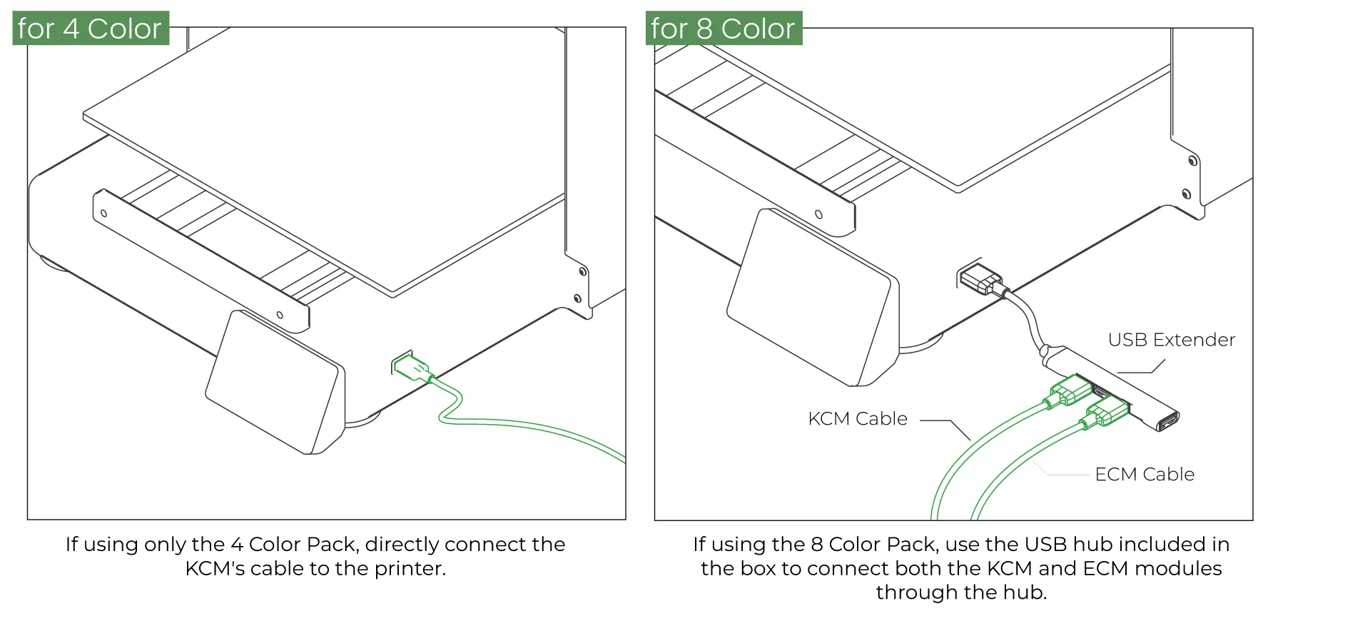
If using the 4 Color Pack, connect only the USB cable from the KCM to the printer. If using the 8 Color Pack, use the included USB Extender to connect both the KCM and ECM cables.
-
Connect the ECM Power, USB, and Motor Cables
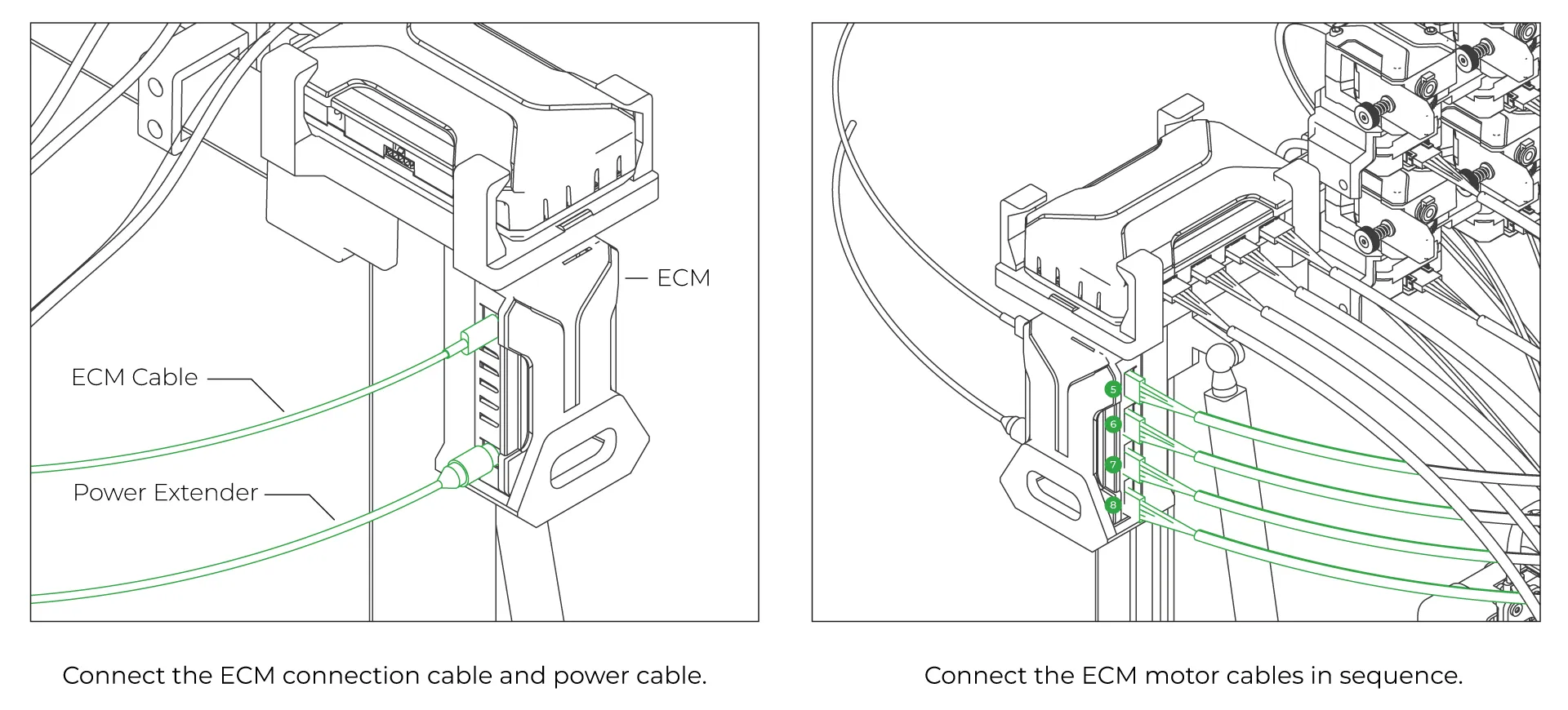
If using the 8 Color Pack, after connecting the ECM module, connect the ECM connection cable and power cable. Then, connect the motor cables in the specified order
-
Connect the 8 Pack Extruder Cables
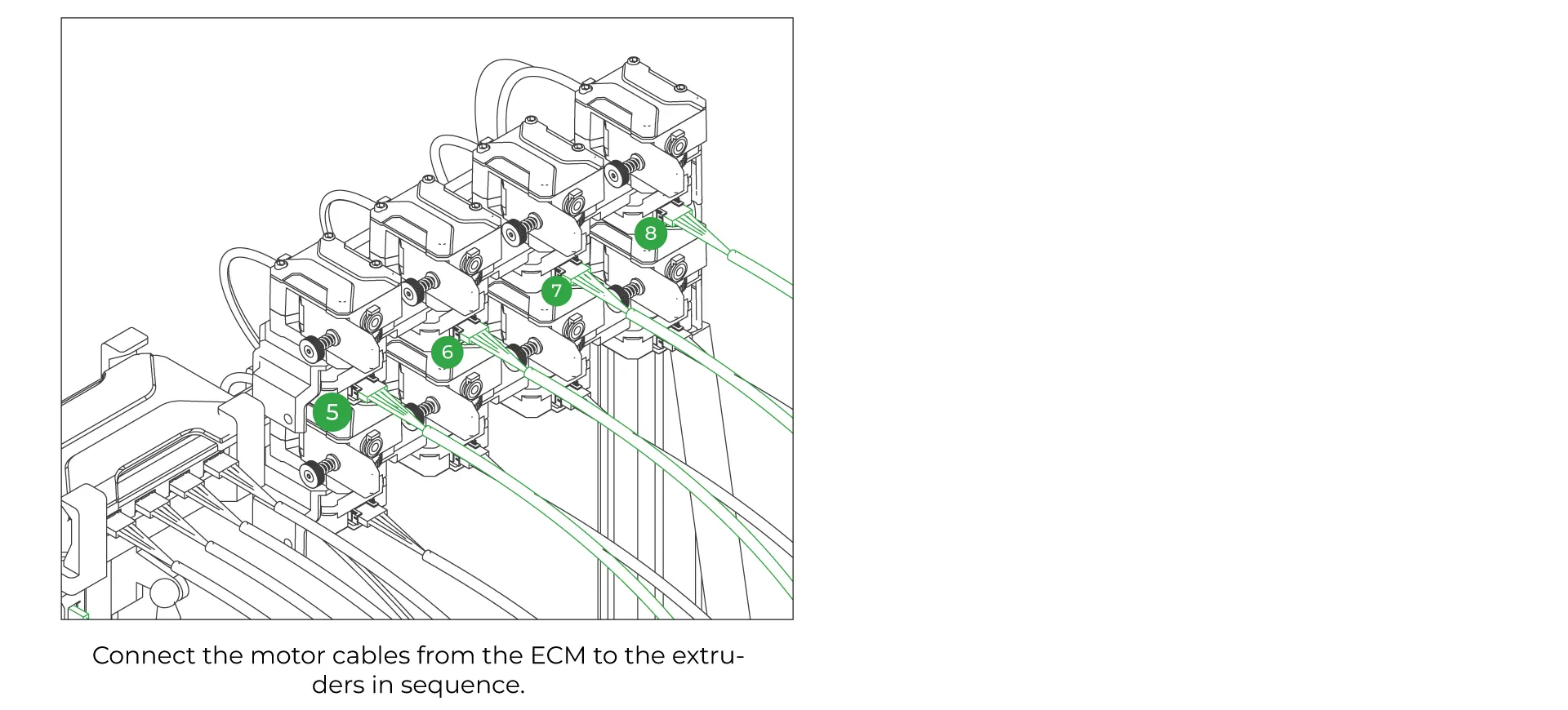
Connect the extruder motor cables to the slot located at the back of the CX-I Extruders, following the sequence specified below.
-
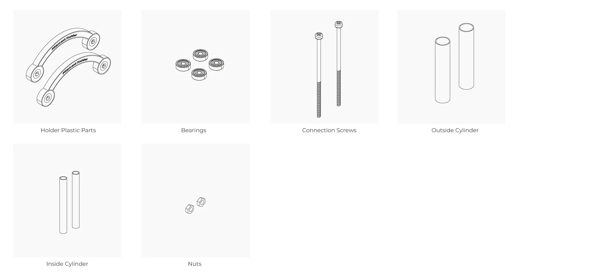
Filament Holder Parts
Filament holder accessories are included in the box to place the filaments and easily rotate and use them. You can find the required components for each holder listed below.
-
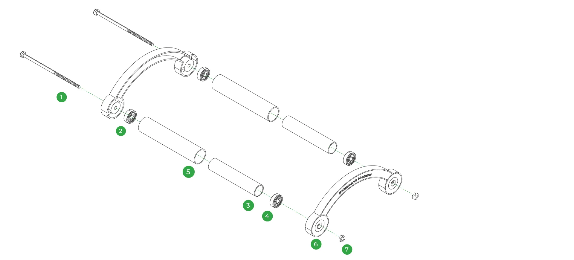
Assembling the Filament Holder
First, pass the long screws through the number 2 left plastic part. Then, insert the bearings included in the box and thread the screw through them as well. Assemble the large and small cylindrical parts by fitting them together, and then add the other bearing and plastic part to complete the assembly. Finally, place the nuts on the ends and tighten the screws.
-
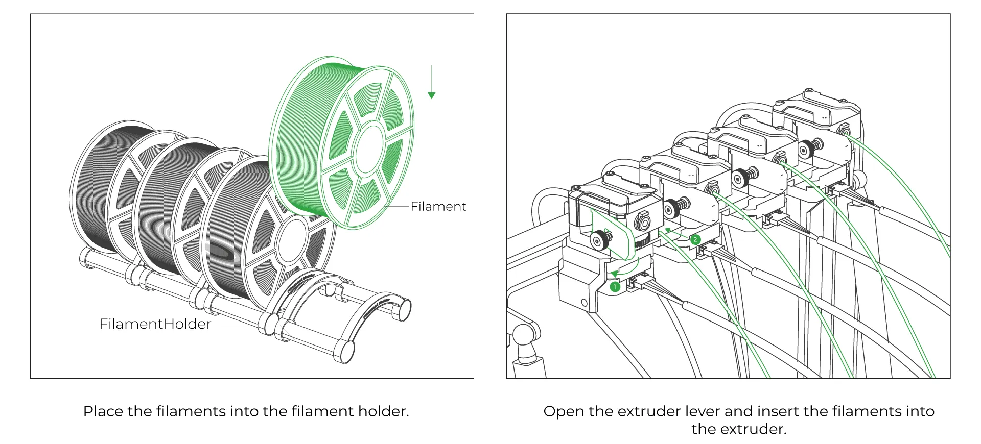
Load the filaments
Before starting the print, load the filaments and attach them to the extruders
-
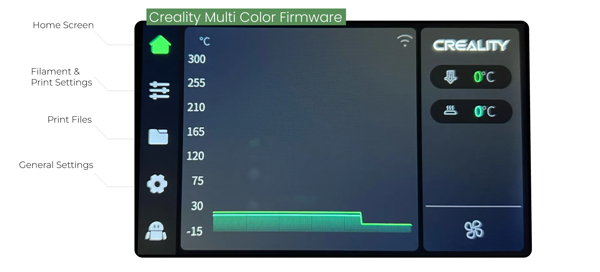
Creality Printer Firmware
After completing the mechanical assembly, power on the printer. The screen will turn on, and once it loads, you will see the main interface. This is the home screen of the software. From here, you can access Filament Settings, Print Files, and general settings to modify parameters such as temperature. To configure the KCM Set, navigate to the Settings page.
-
Creality Printer Firmware
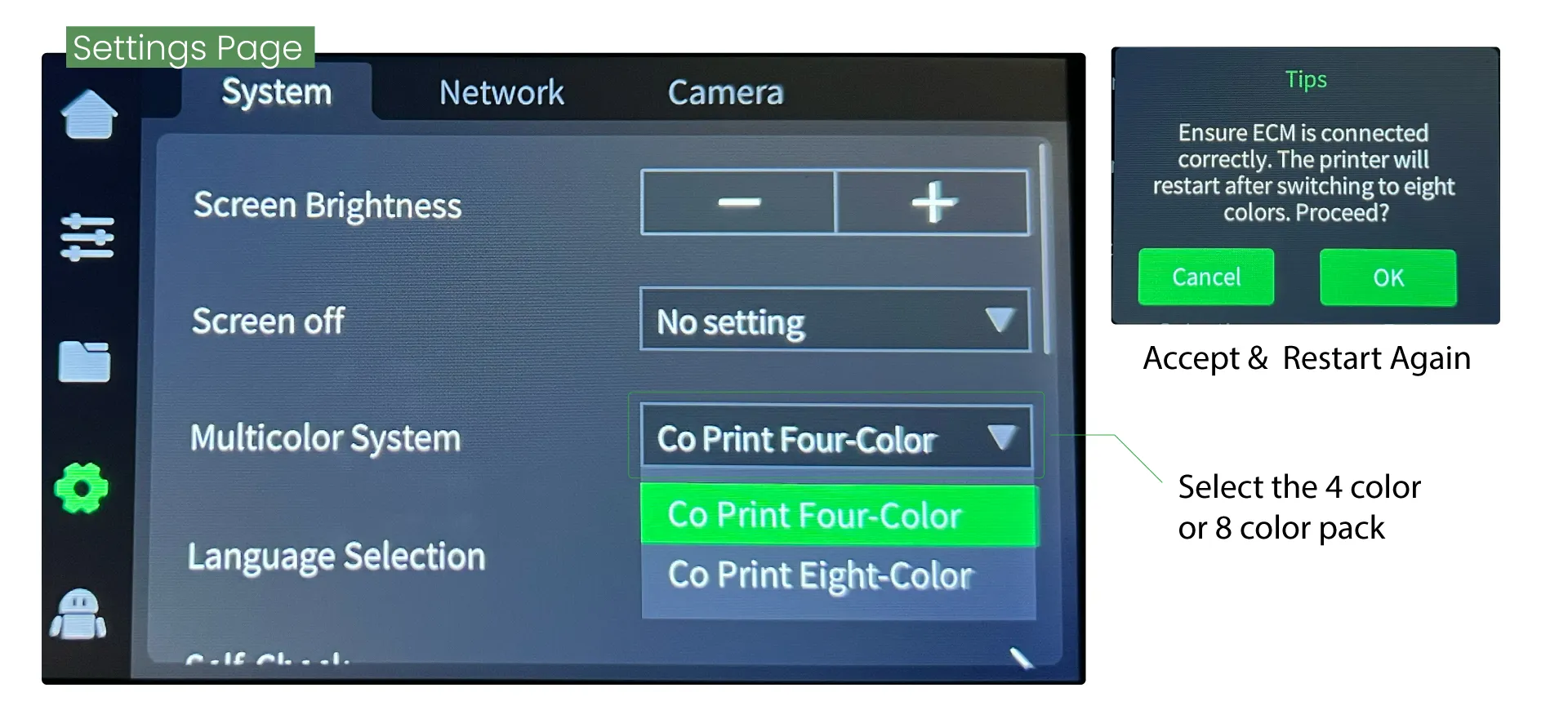
n the System tab on the Settings page, select either the 4 Color or 8 Color option under the Multi-Color System section. After choosing your setting, restart the system.
-
Filament Settings
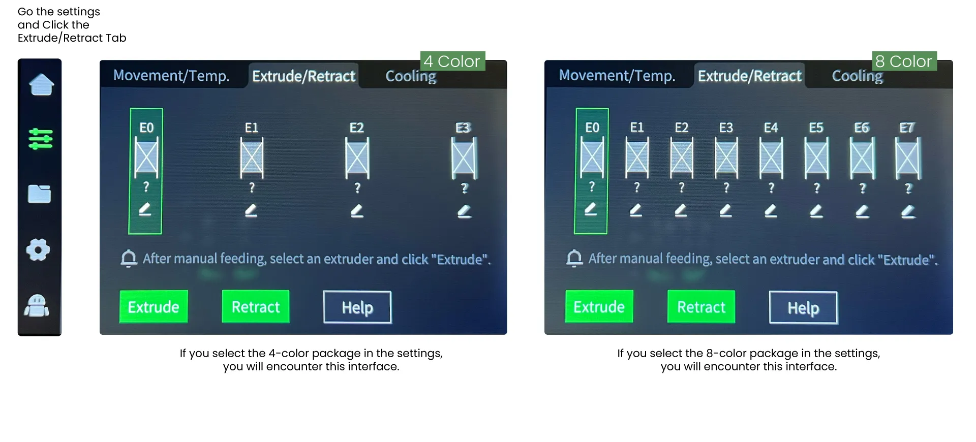
Click on the second option in the menu on the left to open the Print Settings. In the Extrude / Retract menu, you can see the filament options. From here, you can assign, load, or retract filaments.
-
Assign Specific Settings on a Filament
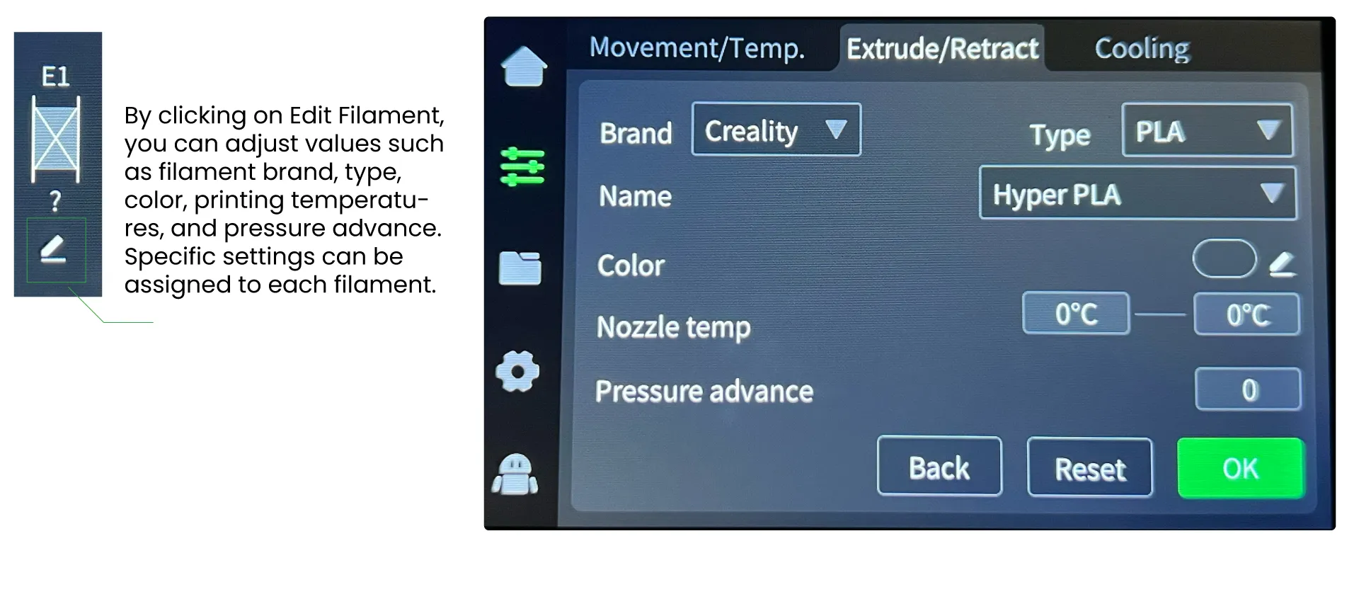
Filament settings are crucial for printing. Before starting a print, you can specify the settings for each filament individually.
-
Control the Cooling Fan
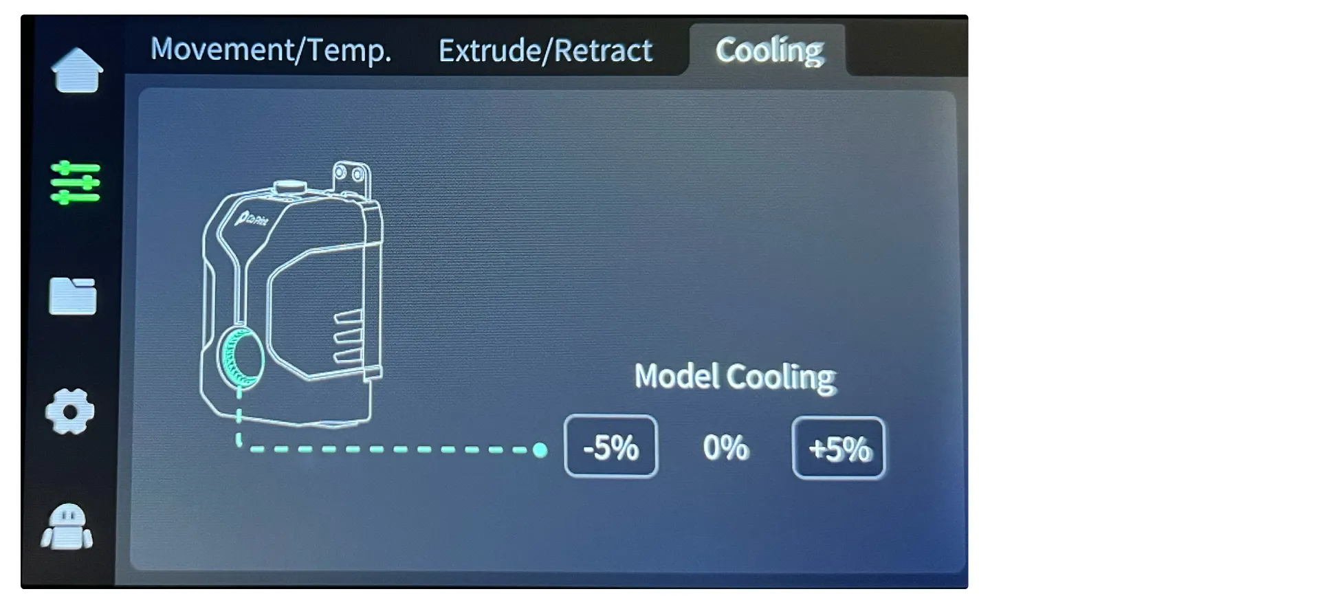
In the Cooling tab, you can control the operating speed and percentage of the part fan located on the front cover of the ChromaHead.
-
Access the Fluidd Interface
From the Network tab on the settings page, connect your 3D printer to the network. Once connected, the IP address (e.g., 172.20.10.3) will appear. Enter this IP address into your browser to access the web interface.
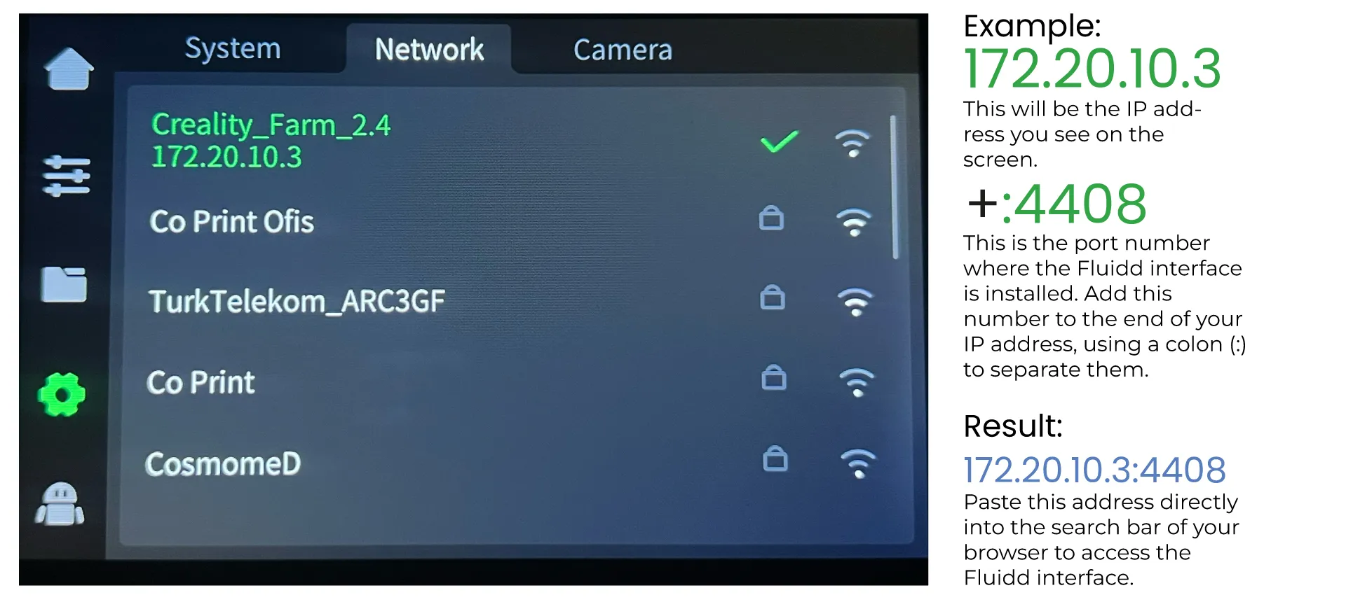
-
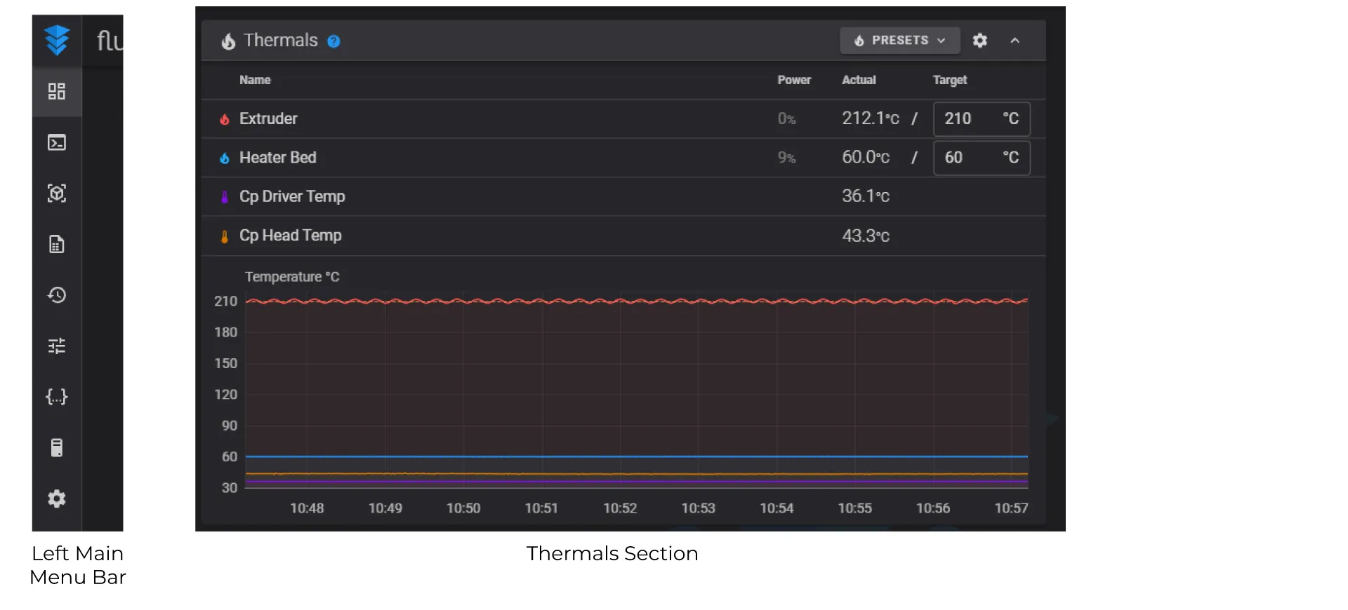
Access the Fluidd Interface
From the Network tab on the settings page, connect your 3D printer to the network. Once connected, the IP address (e.g., 172.20.10.3) will appear. Enter this IP address into your browser to access the web interface.
-
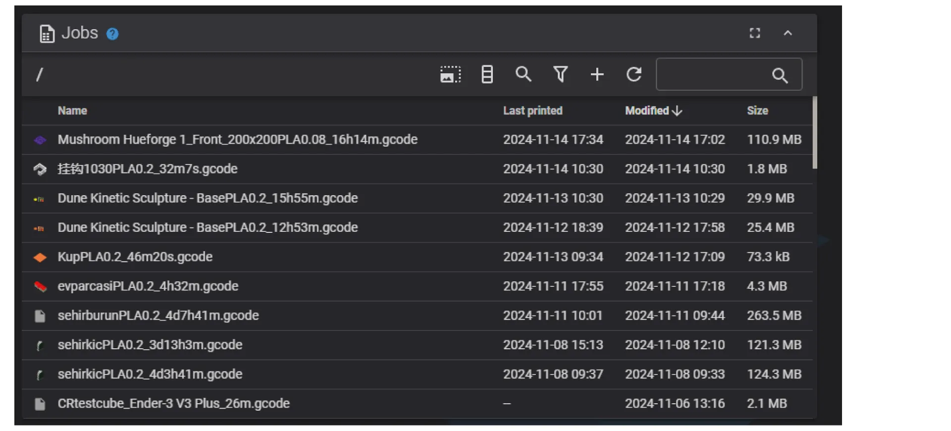
Jobs Section
You can control your printing in the Standby section in Fluidd. After uploading a G-code file to Fluidd, it shows up in Standby section. By clicking on any. gcode file in Standby section, you can start a printing process.
-
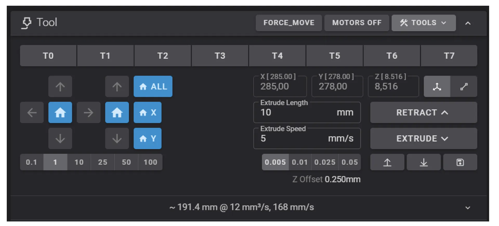
Tool Section
In the Tool Section, you can auto-home all axes and move them manually. Additionally, you can view all extruders and send commands to feed or retract filament on the selected extruder. You can also adjust the Z offset and turn off the motors.
-
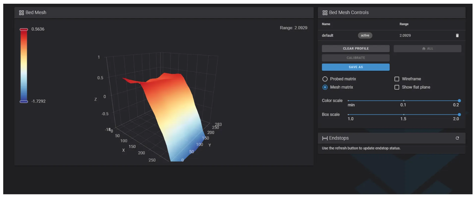
Bed Mesh Calibration
On “HEIGHTMAP” menu, you can calibrate a new bed mesh, or upload the bed mesh that you already calibrated.
-
History & Printer Stats Sections
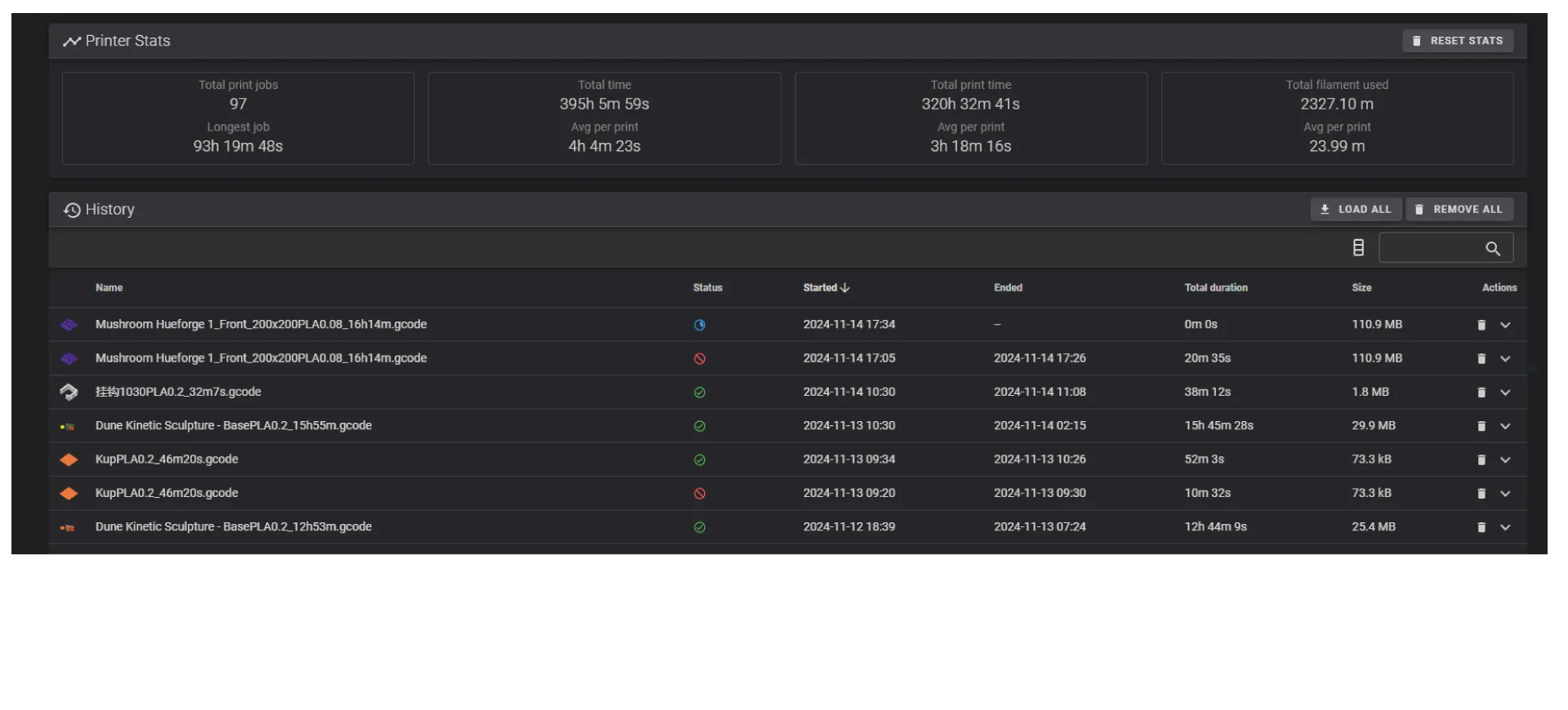
In the History section, you can access information such as your total printing time, the number of successful and failed prints, your longest print, and your total filament usage.
