¶ KCM Set Setup Guide
Welcome to the initial setup guide for KCM Set. Complete the setup by following the steps.
¶ 1. Connect ChromaHead to the 3D Printer
¶ 1.1 Remove old Toolhead & carriage
To attach ChromaHead to your printer, you need to remove the stock toolhead that came with your printer. You can learn how to remove the stock toolhead in the case of the Ender 3 V2 by watching a video. For other printers, you can click here to get detailed information.
¶ 1.2 Attach the ChromaHead carriage to the Sigma Profile and Non-Sigma Profile
¶ Sigma Profile
You need to install the specially designed carriage for ChromaHead that came with the ChromaSet in place of the removed stock carriage. Since this carriage uses stock screws, nuts, and wheels, installation is straightforward. Use an allen key and a wrench to perform the installation.
¶ Non-Sigma Profile
The situation is exactly the same for non-Sigma printers. You can use the part specially designed for your printer by printing it from your printer. Click to go to printable parts.
¶ 1.3 Install the belt onto the carriage
After attaching the screws and wheels, we pass the belt through the points on the carriage.
¶ 1.4 Remove the Front Cover of ChromaHead
To attach ChromaHead to the carriage, the necessary screws are located inside the cover. Therefore, we start the assembly process by removing the front cover.
¶ 1.5 Align ChromaHead with the carriage
After removing the cover of ChromaHead, align it with the carriage attached to the Sigma Profile and insert the screws into the aligned screw holes.
- Sigma Profile
- Non-Sigma Profile
¶ 1.6 Secure ChromaHead to the carriage
After aligning the carriage with ChromaHead, use the M3 screws provided in the set to secure ChromaHead to the carriage at the indicated locations.
- Sigma Profile
- Non-Sigma Profile
¶ 1.7 Installation of ChromaHead Cable
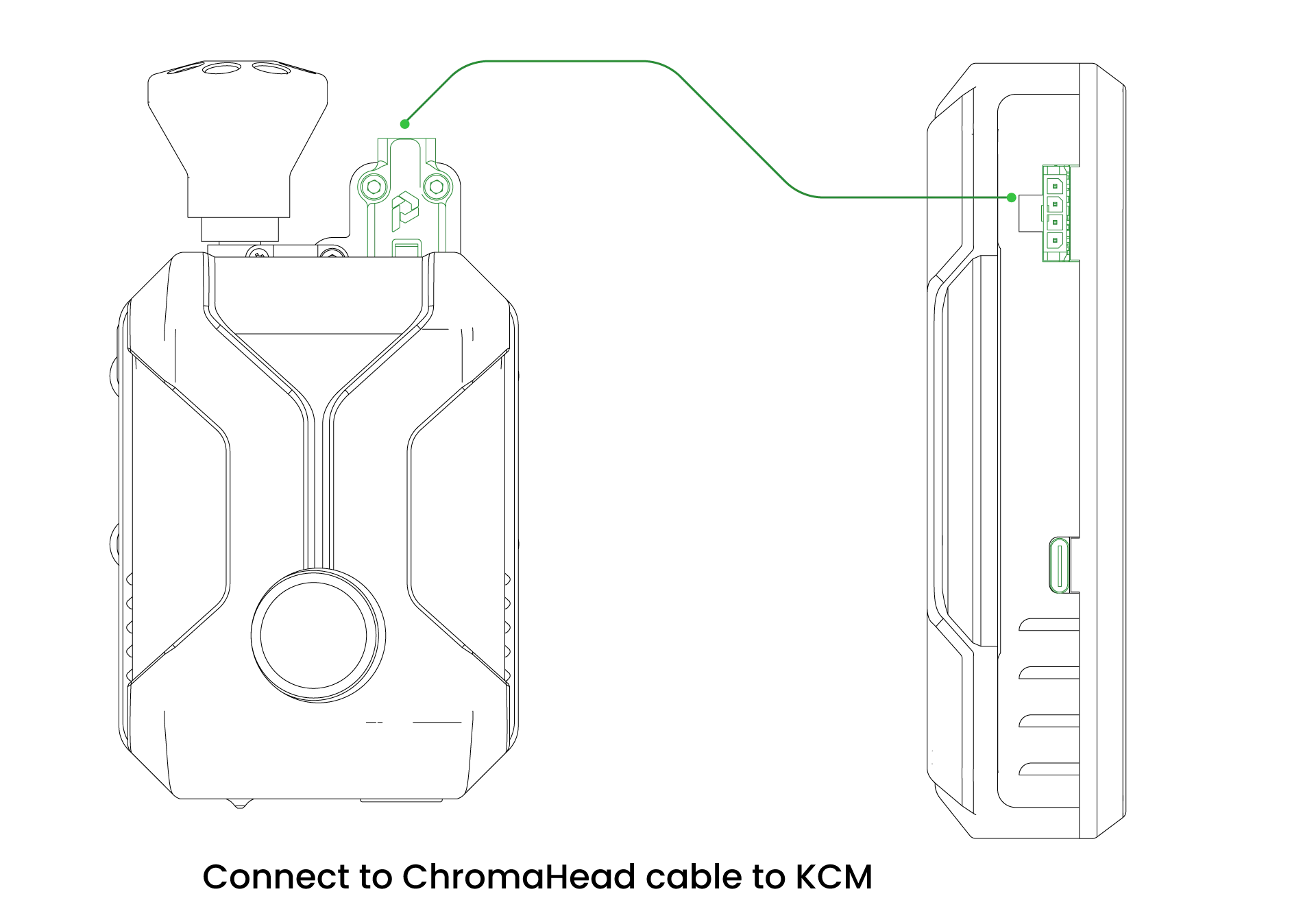
In this step, we're attaching the ChromaHead connection cable that comes with the KCM Set and securing it with the screws provided in the set.
Insert the other end of the ChromaHead cable into the ChromaHead slot located on KCM.
¶ 1.8 Installation of 8 in 1
To connect the filament, rotate the 8 in 1 module and insert it into the threaded socket.
¶ 2. Connect the extruders to the 3D printer.
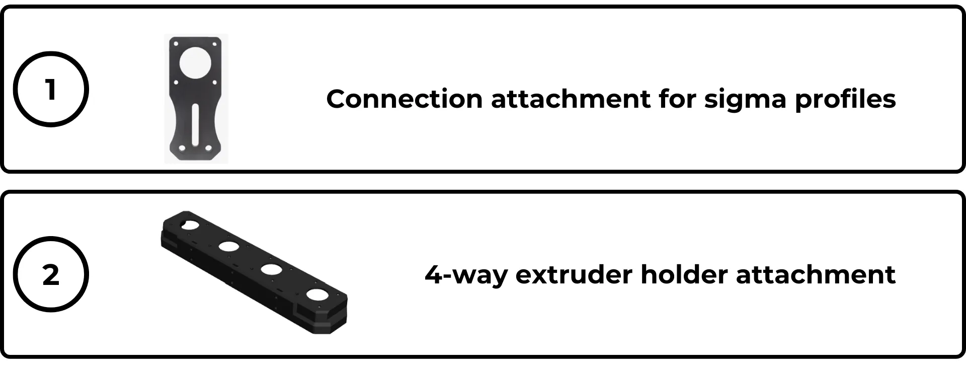
Remove the CX-I Extruders from the box. If your 3D printer includes a sigma profile, use the Sigma profile adapter to make the connection. If there is no sigma profile, use the 4-way Extruder adapter to place it on the table. For printers with a special chassis, you can directly attach the 4-way connection device to the printer using the hook attachments.
¶ Mechanical Connection Accessories for Extruder
We diversified the extruder connection accessories to be usable with different chassis and sigma profile types.
-
The accessory is commonly used to secure one extruder to Sigma profiles as a standard.
-
4-way Extruder Holder: This attachment features a structure capable of simultaneously holding 4 extruders. It's perfect for mounting extruders on printers without Sigma profiles. Different hooks can be attached to the front screw sockets, allowing compatibility with various 3D printers, such as models like K1. Additionally, if you wish to position the extruders on the table, you can easily do so using this attachment.
1.Download the Multi-Connection Attachment
¶ Extruder assembly for the multi attachment

¶ Mounting the Sigma Connection Adepter
Place the screws and T-nuts onto the CX-I Holder piece, designed to mount the CX-I Extruders onto the Sigma Profile.
¶ Place the CX-I Holder onto the Sigma Profile
Hold the T-nuts parallel to the channels of the Sigma Profile and insert them into the profile. Then, place the Holder.
¶ Tighten the connection screws
The screws on the Holder are tightened using an Allen key. The Holder is then secured onto the Holder Sigma profile.
¶ Place the CX-I Extruder
The CX-I Extruder is placed on the upper surface of the holder. From the bottom surface, the Extruder motor is also positioned. The shaft of the Extruder motor and the gear on the shaft fit into the CX-I. Following this step, screws are tightened using an Allen key to assemble all parts of the extruder.
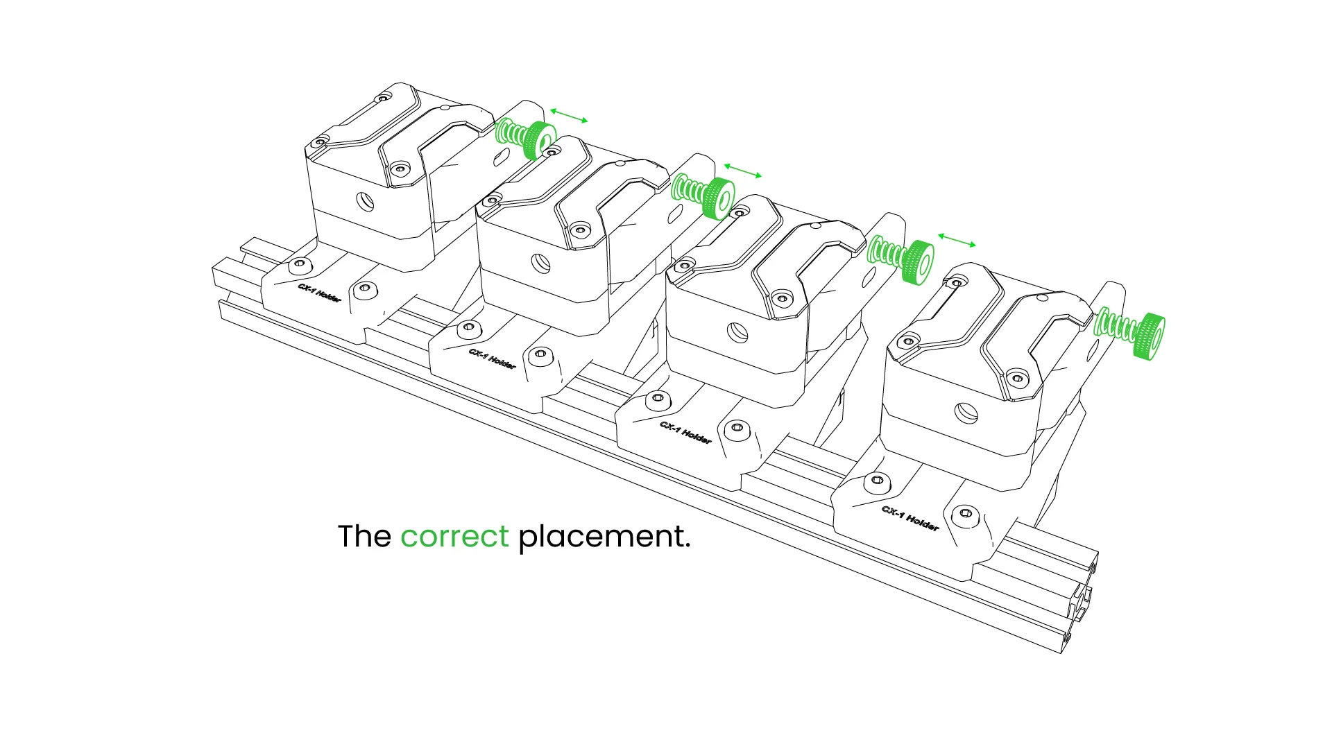
¶ Correct Positioning of CX-I Extruders
You can place the 4 extruders that come out of the ChromaSet onto the sigma profile like this, or if you prefer, you can use additional parts to use them on the table. During placement, adjust the distance between the extruder clamps to ensure comfortable use.
- Sigma Profile
- Non-Sigma Profile
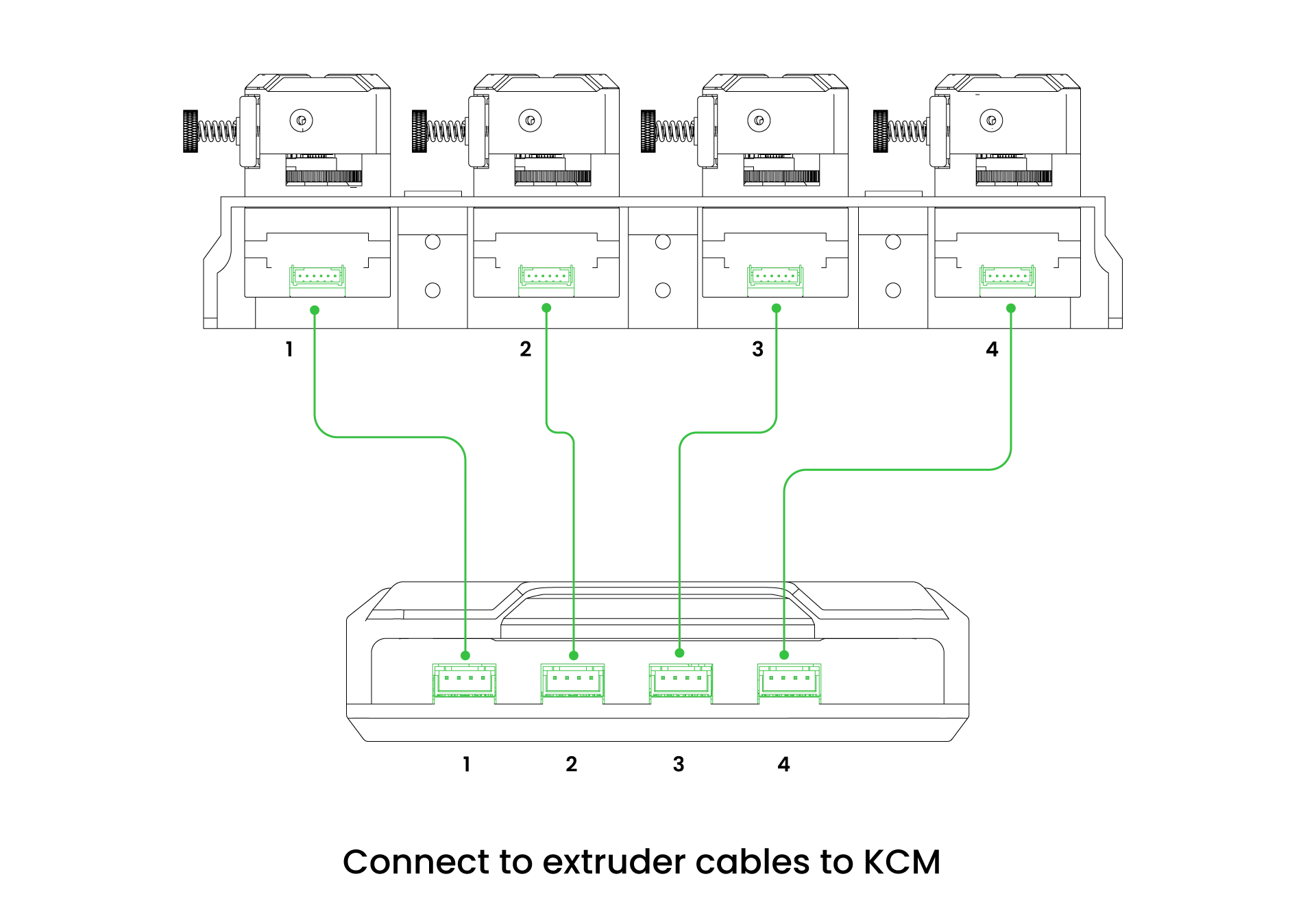
¶ Attach the motor cables to the KCM
We continue by connecting the cables of the products we have made mechanical connections to the KCM. First, we place the motor cables sequentially onto the extruders, and then onto the slots located on the KCM.
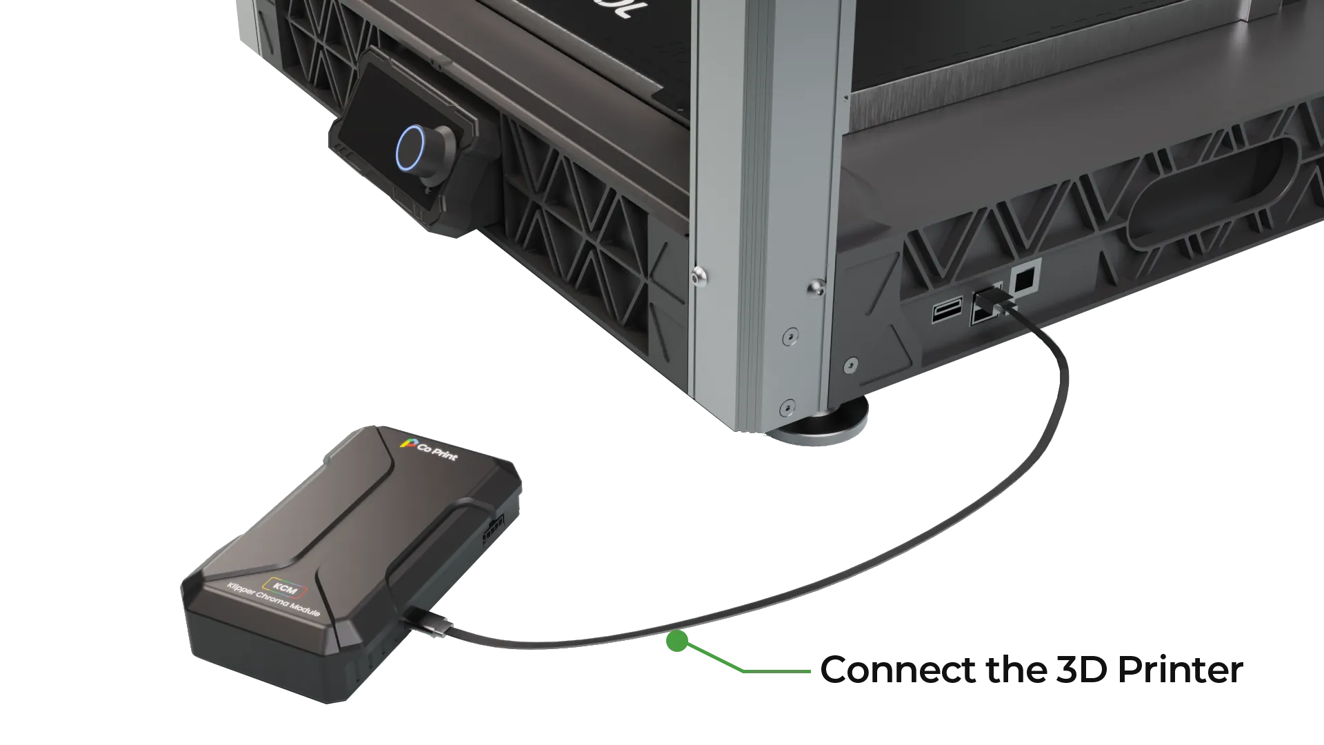
¶ Connecting the 3D printer to the KCM via the USB cable
Finally, we establish the cable connection from the KCM's Type C port to the printer's USB port.
¶ Powering the KCM
Now that we have completed all cable connections, we can power up the KCM. Use the power socket and the adapter provided in the box to connect the KCM module to power.
¶ KCM Settings Files
The KCM set requires five configuration files to use in Klipper systems. These configuration files are:
[bed_mesh.cfg][chroma_head.cfg][cp_macro.cfg][input_shaper.cfg][kcm.cfg]
- You can download the necessary configuration files from Here.
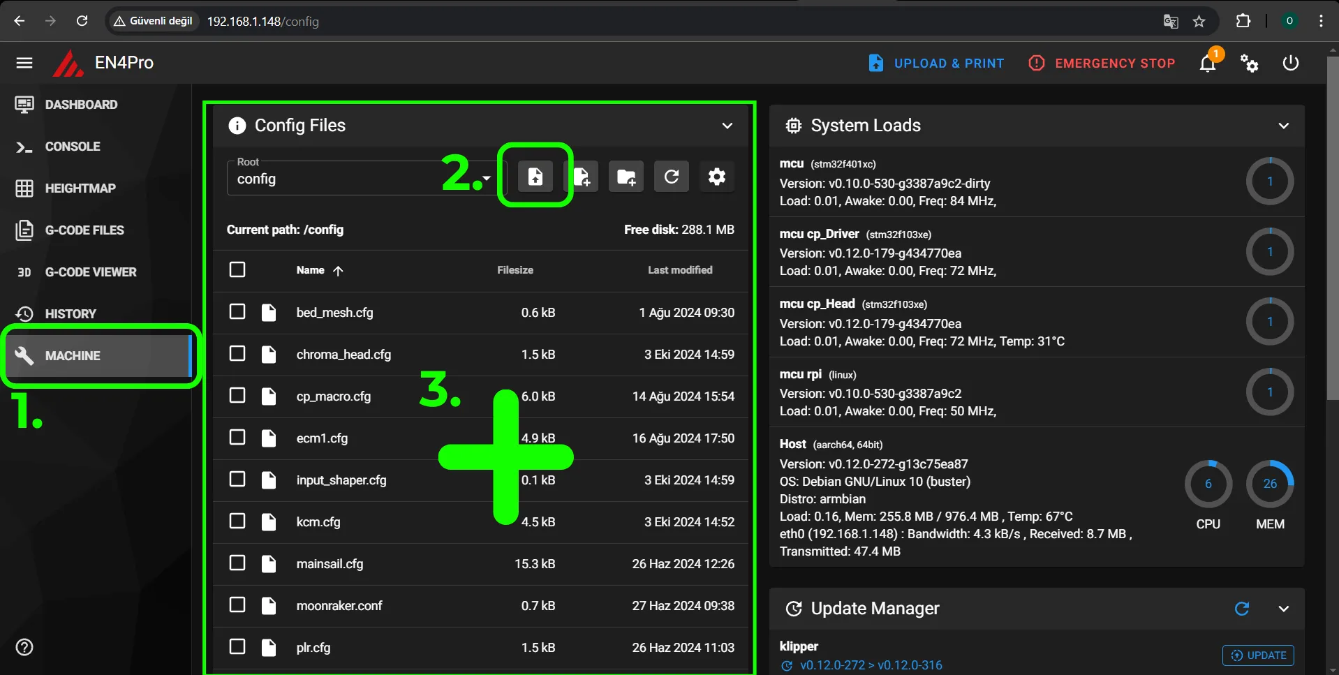
These files contain specially written settings for KCM set functions. After downloading these files, connect them to your 3D printer's web interface, then upload them to the 'Config Files' section under the 'Machine' tab in Mainsail.
Navigate to the 'Machine' tab in Mainsail, then proceed to the 'Config Files' section and upload the files.
¶ Remove conflicting parameters from printer.cfg
The "chroma_head.cfg" is the configuration file containing parameters controlled by the KCM. KCM controls parameters such as the extruder motor, 2 fans, filament sensor, Z limit switch, etc. These parameters also exist in your existing "printer.cfg" file. If conflicting parameters in "printer.cfg" are not removed, the system will produce errors. To remove conflicting parameters:
Navigate to the Printer.cfg file within the Config Files section of the Machine tab in Mainsail.
The translation of the term found in Printer.cfg is:
[mcu]
[stepper_x]
[stepper_y]
[stepper_z]
[heater_bed]
[printer]
All parameters are left unchanged, and the remaining parameters are deleted.
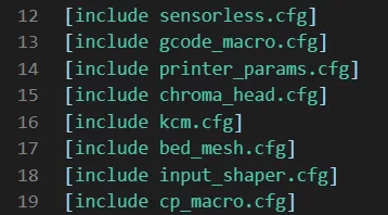
To allow the parameters from the uploaded files to replace the deleted ones in Printer.cfg, we need to introduce the files we uploaded to the Printer.cfg file using the [include] parameter.
[include chroma_head.cfg]
[include kcm.cfg]
[include bed_mesh.cfg]
[include cp_macro.cfg]
[include input_shaper.cfg]
We've defined these five files we uploaded to the system within Printer.cfg. Click on the Save & Close button to exit.
¶ 9- Defining the USB path of the KCM and ChromaHead to Klipper
Now, we need to define which USB port the KCM is connected to within kcm.cfg. To do this, while inside the kcm.cfg file, click on the Devices button in the top right corner of the screen.
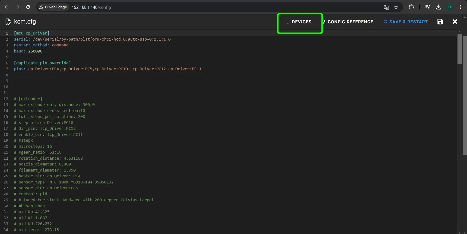
In the opened Pop Up, click the refresh button once under the Serial tab. Initially, the USB path may not appear. After clicking the Refresh button, the data should appear.
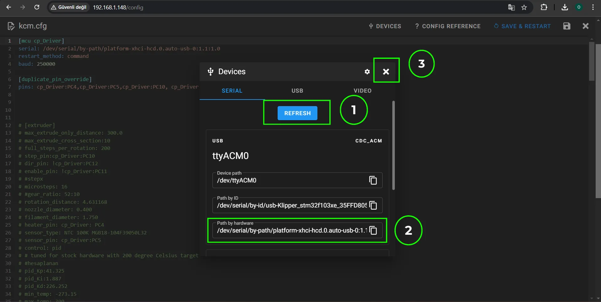
After clicking the button, copy the Path by hardware under ttyUSB10. In this example, the path is: /dev/serial/by-path/platform-xhci-hcd.3.auto-usb-0:1.1:1.0-port0. Preserve the quoted structure when writing paths and parameters.
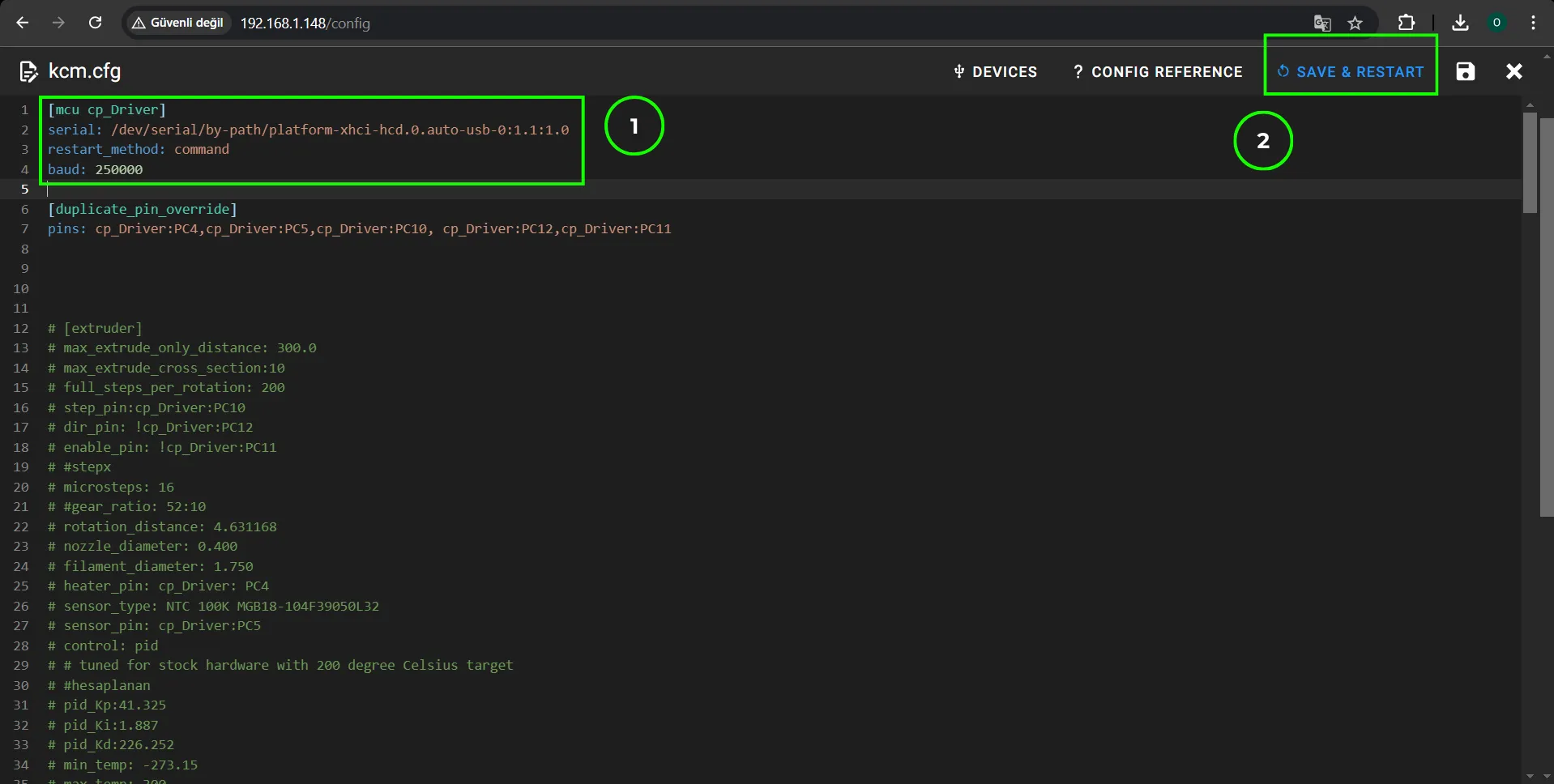
Closing the Pop Up, paste the copied path into the 'Serial:' parameter under [mcu cp_Driver] in kcm.cfg.
Click the Save & Restart button to close this file and save the settings.
In the opened Pop Up, click the refresh button once under the Serial tab. Initially, the USB path may not appear. After clicking the Refresh button, the data should appear.
Determine the path of ChromaHead. and then past it to number 3 in the picture shown below.
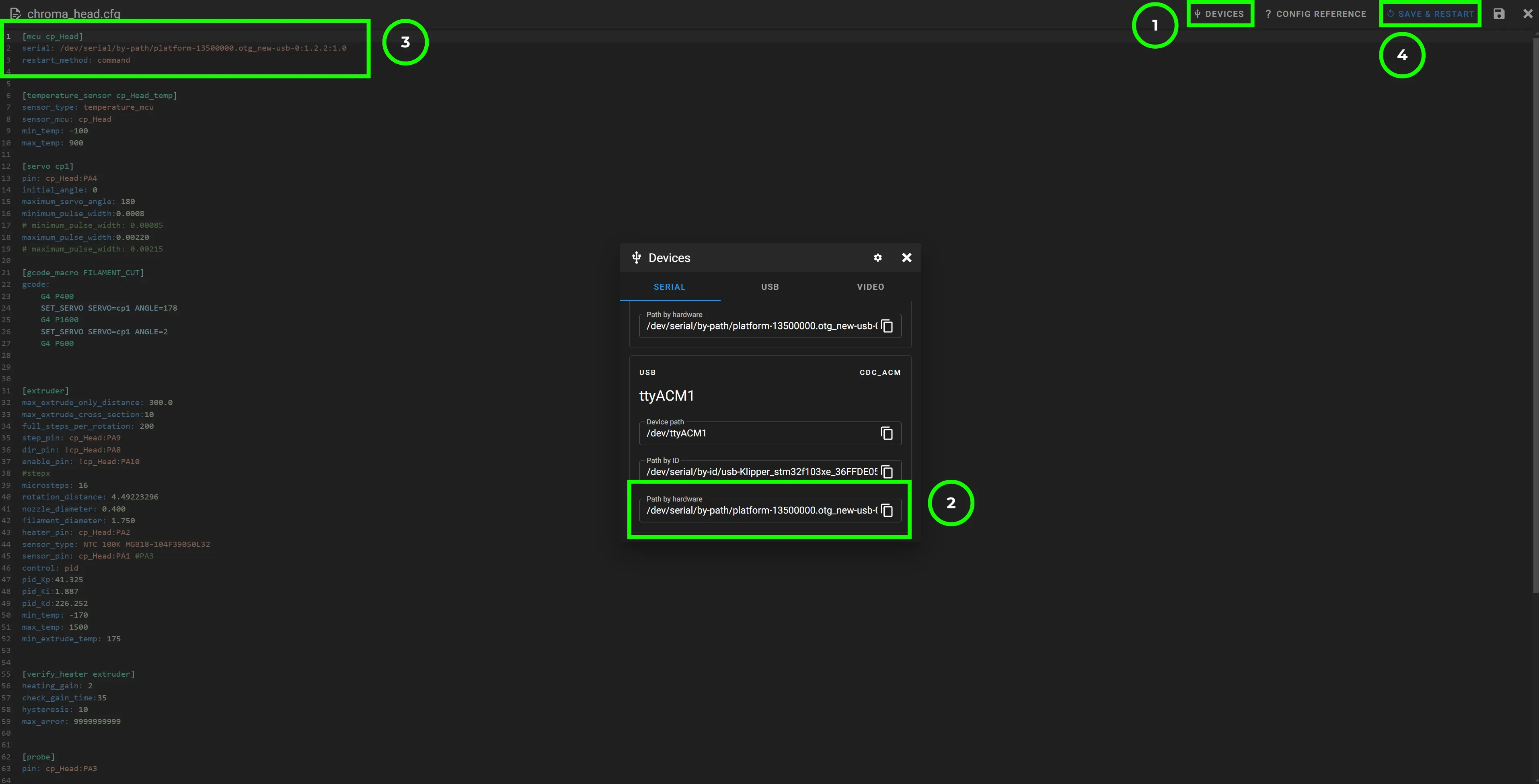
Click on SAVE & RESTART
Your KCM Set is ready to use. Click here for a tutorial on how to take your first color print.